GIMPy text

Oct. 2nd, 2024 03:00 pm
pheloniusfriar: (Default)
How to draw text around a circle in GIMP, and 101 other reasons I hate my life.

  1. Image->Guides->New Guide (by Percent). Place horizontal and vertical guides at 50%.
  2. Make sure View->Snap to Guides is selected.
  3. Using the Ellipse Select Tool:
    1. Left click on centre of guides and hold.
    2. Move mouse to show ellipse.
    3. Press Ctrl + Shift to use guides as centre and make it a circle.
    4. Position circle edge to middle of where text needs to go.
    5. Release left mouse button.
  4. Select->To Path to create a path.
  5. Select->None to remove selection (path will remain in Paths tab of layers list).
  6. Go to Paths list tab of Layers list and turn on visibility of newly created path (it will show as a red circle).
  7. Using the Text Tool:
    1. Select the Font, Size, Color [sic], and spacing desired.
    2. Type in desired text (a bit away from the path is best).
  8. Go to Layer list:
    1. Select the layer for the text just created.
    2. Right click and choose “Text along Path” to wrap it around circle.
      • If it is backwards: Edit->Undo Add Path (or Ctrl-Z). To fix direction:
        • Select the Flip Tool (it's in the same tool group as the Rotate Tool and other transform tools).
        • Click on the Transform: Paths button in the tool configuration.
        • Go to the Paths lists and select the path for the circle.
        • Click on the circle path in the image to flip its direction.
        • Try Step 10 again... the text should go the other way around.
  9. Create a new layer and make sure it is selected.
  10. Go to Paths list, right click on new text path, choose “Path to Selection”.
  11. Choose desired foreground colour, Edit->Fill with FG Color.
    • The visibility of the original text layer and path for the text can be turned off.
    • Selecting Select->None will clean things up visually at this stage as well.
    • Alternately, you can just delete the original text layer and path.
  12. Make sure new layer with text is selected:
    1. Do Select->None (if not already done) to allow whole layer to be rotated.
    2. Use Rotate Tool to move text to final position (make sure the Transform: layer button is selected in tool configuration).
      • Grab layer anywhere with left mouse button and move mouse to rotate.
    3. Press Enter to exit the Rotate Tool mode.
  13. Select the layer just rotated from the Layers list, right click, select “Layer to Image Size”
  14. Repeat from Step 7 for any additional text.

A video by the most excellent Nick is here (he really explains the details, which I love):
pheloniusfriar: (Default)
Since I've been doing my "radio show" on YouTube, I've been developing tools in bash script (shell scripting) that allow me to use the YouTube API (v3) to automatically extract information from my playlists and store them in files formatted in a way useful to me. In particular, as I'm putting a show together, one of the key things I need to know is how long it is. In my case, I have specific sorting I need to do to separate between the commentary video I do and the music itself, but I needed a generic script that let me just do it generically for any playlist (with no special sorting). The script uses standard Linux utilities plus "curl" to do the API queries. If it isn't clear, the YouTube API is URL-based. One of the big things I needed to figure out is that YouTube will return a maximum of 50 entries for a query, so it provides a "nextPageToken" that needs to be used to get the next 50 (or less) entries. I start with my nextPageToken as as empty string (YouTube accepts an empty value and returns the first page), and then set the nextPageToken variable to the value returned for the next page's token (gasp!). When the results don't contain a "nextPageToken" keyword, it's the last page and I use that condition to exit the loop.

The script has three major parts: getting the basic playlist info, getting the full contents of the playlist tracks (in particular names and IDs), and then it uses the IDs to get the time information for each of the tracks in the playlist. It builds it all into one file with a header containing the title and summary information, and the a list of the tracks with times. These are stored in the file "./playlist/<playlistID>/playlistInfo.txt (backups are kept of previous runs for each playlist in the same directory). The directories are automatically created. You'll need to get a developer account with YouTube to get a token of your own before you can run this script. If you want to find out how it all works, comment out the file deletions and look at the intermediate results or, even better, run the "curl" commands from the command line and see what comes back (the results are in a JSON format that I parse directly).

The script takes one parameter: the playlist ID. If you go to a YouTube playlist, the playlist ID is the parameter in the URL of the playlist that comes after the "list=" directive and starts with a "PL" (you need to specify the PL as well in the playlist ID). You will, of course, need the rights to read information from a playlist. I'm only running it on mine, so I don't know what the result would be if you ran it on a playlist of mine (I'd be curious).

To invoke it on the playlist I have at the bottom of the post (my show Season 1, Episode 11), I would use:
./getArbitraryPlaylist.sh PLcbc6Su4uUe8VxRCRH74ZO8_mgsPOkGQx
The playlist has 15 entries in it and runs for 1h10m07s (all the videos including my parts).

The output I get is:
URL: https://www.youtube.com/playlist?list=PLcbc6Su4uUe8VxRCRH74ZO8_mgsPOkGQx
Title: "S01 | EP11 – The Passionate Friar on YouTube (2021/07/11)"
Published: 2021-07-03T23:33:42Z
Track Count: 15
Total time: 1h10m07s

5:33 – S01 | EP11 | COMMENTARY No. 1 of 4 – The Passionate Friar on YouTube
1:36 – Hell - Clown Core
3:05 – Valentino Khan - Deep Down Low (Official Music Video)
2:37 – IGORRR - VERY NOISE
6:27 – S01 | EP11 | COMMENTARY No. 2 of 4 – The Passionate Friar on YouTube
4:08 – Khruangbin - Evan Finds The Third Room (Official Video)
6:16 – Kamasi Washington - Street Fighter Mas
3:59 – Chelou - Damned Eye See (Official Video)
4:28 – Mcbaise - Water Slide (feat. Kamggarn)
6:14 – S01 | EP11 | COMMENTARY No. 3 of 4 – The Passionate Friar on YouTube
3:15 – Siouxsie And The Banshees - Peek-A-Boo
4:26 – Depeche Mode - Never Let Me Down Again (Official Video) (Heard on Episode 1 of The Last Of Us)
3:36 – FKA twigs - How's That
3:39 – S01 | EP11 | COMMENTARY No. 4 of 4 – The Passionate Friar on YouTube
10:48 – Animal Collective - Bridge To Quiet (Official Video)
And here's the script itself (if you have any questions about it, I'll try to answer if you ask):

the code... )

Example YouTube playlist (my show, Season 1, Episode 11):

pheloniusfriar: (Default)
If you can imagine such a thing... gasp!

The 1TB Seagate drive in my main system (a Barracuda ST1000DM003) was failing (lost some data, but not much, I copied stuff off to an external USB drive before it totally died). Even the Seagate disk diagnostics software couldn't run tests on it. In some senses it didn't owe the world anything as it was quite old, but the whole point of modern drives is they're supposed to handle bad block management for you and you're not supposed to lose data that way anymore. That didn't seem to work very well (trying to read those files with damage actually bluescreened Windoze, but that's another matter... I used Linux and "ddrescue" to get the good data off with no problem). I took the drive apart and found that the reason it failed was due to corrosion on the contacts between the interconnects! There was a materials incompatibility between the two sides of the connection and it ate away at the printed circuit board. I consider this a serious engineering failure. The photo on the left is the signal connection, the one on the the right is the power connection.


I replaced the drive before I had taken the old one apart (it took me a while to get the data off the disk), and because it's Windows, I pretty much had to do a fresh install from scratch (there are other reasons with Windows to want to do that as well). When I bought the replacement, I did some research and didn't really find any reason not to buy another Seagate, and the 4TB one I got was a good price, and on sale. Not crazy cheap, just a few bucks off, so meh. If I'd taken the old drive apart before I bought the drive, I certainly would have thought twice about getting another Seagate!

Easy peasy, right? No. Not. Not at all. I bought a Seagate ST4000DM004 thinking it would be a larger (4TB) and fairly direct drop in replacement to the one I pulled out. Since then, I've noticed that my system performance has been pure shit. I generally blame Windows, and I have learned the way it operates is partially to blame, but the source and destination of the issue was the accursed ST4000DM004. On my Discord server, I wrote what follows this paragraph (I've deleted it and just put a pointer here). tl;dr Don't ever buy a "Shingled Magnetic Recording" (SMR) and if you can't tell if it is or not ... don't buy it either! Know before you buy!

Well, fuck. I apparently missed the memo and there's a new computer disk type: "Shingled Magnetic Recording" (SMR)... and I can report that it sucks farts from dead cows. I'm seeing average response times on the disk in my main computer system often in the order of 4500ms ... 4.5 seconds (seconds!) as I try to do insane things like... oh, install software... or, nuts like trying to copy a file. I went searching for my hard drive model, the Seagate ST4000DM0004, because what I was seeing just didn't make any sense. Step one: never, ever, ever, buy an SMR drive unless you know exactly what you're getting into (they are reported to be okay for archival purposes or backup, but I'm not even convinced about that). Apparently, it's a way of stuffing more data onto a platter by overlapping tracks, but it means that individual sectors can no longer be written... the disk has to re-write large swaths of itself to change a sector because it has to encode the data to allow the tracks to overlap (it has to read the block, which people claim can be gigabytes in size, but I have yet to confirm that... although what I've seen does make it believable... then make the change to the one 512 byte sector, then write it all back again). What it does is it has a non-overlapping set of tracks around the outer edge where it writes data to, a sector at a time, and then what it's supposed to do is read/modify/write the large block of overlapping tracks it's in... nominally when the disk is not too active. I'm guessing it can also merge modifications for a particular large block if a bunch of sectors on the "disk cache... not memory, but bits on spinning metal". I'm further guessing that if you keep writing to the same sectors in that staging area, it defers the big updates of large blocks until the writing stops to the sectors destined for a shingled write. But... when the "cache" is full, it has to flush those sectors to the disk (read/modify/shingle write a large area) before it can accept any more data. And I think that is what I have been repeatedly seeing during normal operation.

This sucks, and I paid good money for a piece of shit drive. Don't buy these drives! Don't be like me! 🪦

"Unfortunately, all three of the remaining HDD vendors decided that the way they would release this technology is by slipping it into the product lineup without telling people about it. So rather than being able to make a conscious choice whether or not to accept a performance cliff in exchange for a slightly lower cost per unit of storage, people unknowingly received these drives. Since it was all three of the major HDD vendors who did this, you can't just boycott the culprits, so it seems the only option is to carefully check every hard drive you buy from now on."

Question subject: "Extreme drops in hard disk performance"
https://superuser.com/questions/1691661/extreme-drops-in-hard-disk-performance

Google is not providing me with a link to the original of this review, so I'm copying it here:

SMR system drive + Windows 10 or Windows 11 = HORRIBLE performance

"DON'T BUY THIS DRIVE TO USE AS A WINDOWS 10 OR WINDOWS 11 SYSTEM DISK. These SMR (shingled magnetic recording) drives can't write a single sector at a time to the disk because of the overlapped magnetic recording technology they use. The drive ends up writing the sector you try to write to a small temporary storage location on the drive and that is pretty fast, but later it has to go back and rewrite the data to another higher density location on the drive where it will have to rewrite adjacent sectors at the same time because their data overlaps unlike the data on traditional CMR (conventional magnetic recording) drives. As a result of having to write sectors more than one time the drive will thrash (move the recording head around making seeking noises) more than normal, but if the data is written in small bursts and not too often then aside from the extra disk operation that you will hear it will work like a regular drive. The performance problem with this drive occurs when you write too many small bursts of data at the same time as you are trying to read data or you write a large amount of data for a sustained period of time and that temporary fast storage area becomes full. When that happens you have to wait for the drive to write the overlapped data before it can process your next bit of data and the sustained transfer rate of the drive plummets due to jumping back and forth between the fast and the slow part of the disk. I will get sustained transfer rates under 20 MB / sec sometimes when transferring a large number of files. That's almost as bad as a USB 2.0 flash drive. The latest versions of Windows 10 and Windows 11 seem to do a lot of logging. They read and write event log and NTFS filesystem log data to the drive constantly. In Windows 11 my computer was reading over 1 MB/sec of data constantly so this drive keeps jumping around writing sector, read sector, rewriting sector to higher density area, reading sector and latency of all these small operations just crushes the performance of the drive. It takes the latest versions of Windows 10 or 11 a few minutes just to boot up and the disk operations just never end. Its constantly thrashing the drive every second of the day and since its always in the middle of some disk operation, the latency of any disk operation you want to perform is greater because it has to wait for its current operation to end first. Its very unpleasant and completely unacceptable both performance-wise and noise-wise and I'm sure the life of this drive will be shorter than a CMR drive due to the extra operations the drive is having to perform. The drive does hold a lot of data. If you don't use it as your Windows system drive which will be constantly reading and writing log files and you mostly read data from it and not write to it then its decent enough as an archival drive for movie, music, picture, or game storage. It has a lot of capacity and is cheaper than equivalently sized CMR drives. Writing performance of the drive is terrible, but reading is just as fast as other drives provided you haven't written a lot of data recently to the drive causing it to need to rewrite data possibly at the same moment you are wanting to read from it. You really need a SSD for your system drive in Windows 10 and 11 now due to the excessive reading and writing of small event log files. This drive isn't suitable for that purpose. SSDs don't have the seeking latency or noise production of magnetic drives so you won't notice that your SSD is operating all the time. You will regret it if you buy this drive and attempt to use it as your system drive in Windows 10 or 11. You've been warned."

I disagree with the dogma that you need an SSD for your Windows system disk, but I do agree that this SMR disk type is not suitable for that application.

Grrrrr...
pheloniusfriar: (Default)
And finally... a question that did not receive an answer. I'm thinking there might be a way of doing this, but I would need to hear from someone who knows the innards of the PSoC Creator Integrated Development Environment (IDE) on how unless I stumble on some poorly documented back door way of doing it. It maybe impossible from within the component itself though; but it's theoretically possible, and I would view this as a shortcoming of the tool if it's not. Sadly, the tools at Cypress started to balkanize even before they were bought out by Infineon and I'm not getting strong "we'll be supporting these tools going forward" vibes. I'm not plugged in, but it has been over 2 years since the last PSoC Creator update. Not looking good.

Why do I want to do this? If I could get this to work, I could package a UDB-based PSoC component for PSoC Creator to do 16-bit arithmetic with a single 8-bit UDB. I'm a fan of pushing technologies as far as they'll go, so this was a little side project I was working on that was part of a larger project.

I have a UDB component (single UDB) and was wondering how to initialize the associated Auxiliary Control Register from within the component itself without having to do it at the project level with a call to an initialization API function in main() or some other project-level technique? I want to configure the FIFOs of a UDB into their "Single Buffer" mode by writing 0x03 into the Auxiliary Control Register of that UDB (Architecture TRM, section 16.2.3.7), but can't figure out a way of doing that automatically.

Edit 2020/09/16: To clarify, I am trying to initialize that register at the component level, rather than at the project level, so that someone using the component just has to drag it onto their schematic from the component library, and all the necessary hardware configuration would be done transparently by the component itself simply because it has been instantiated (and not require an initialization function to be called in main() or for the startup code to be modified at the project level). This is the case already for everything but that Auxiliary Control Register. The notion was to make the component potentially a pure "hardware" component from the perspective of someone using it in their project from the component library (it has some parameters that can be set from the schematic, and i was hoping that was all that would needed to be done by someone using it).

I saw in the Component Author Guide the ".cy_registers()" function (section 4.3.5 "Fixed Blocks") that "For all fixed blocks, a parameter of cy_registers is available to allow you to explicitly set the values for the given registers for the block. The values listed will be included in the configuration bitstream generated to program the part, which will be established before the main() function is called." This seems to be exactly what I want, but it doesn't seem that the datapath itself allows this parameter. When I look at the .vh2 file created for the component, the instance of cy_clock_v1_0 that I put on my schematic (and wired to my component) has a parameter "cy_registers" (it's empty, but it's listed); but the cy_psoc3_dp I instantiated does not have such a parameter listed. When I tried to add it to the parameter list of the datapath, I get an error.

Is there a "proper" way of doing this from within my component so the value is automagically intialized by the time main() runs? I wanted the component to be able to run without needing to be initialized in the user's software (effectively a pre-configured hardware component), and the FIFO configuration is the only thing I can't seem to access from within my Verilog code (and it won't work without the FIFOs being in the proper mode). I hope I'm just missing something obvious.

I'm guessing that the cyfitter_cfg() function can do it (and is where this should end up), but I can't figure out how to get it in there (there's a BS_UDB_0_0_0_CONFIG_VAL[] array in the cyfitter_cfg.c file that was created that seems to have the UDB config in it, and presumably the Auxiliary Control Register is one of those values). I read through Alan Hawse's excellent IoTExpert article on PSoC startup, and it told me where it would be done, but provided me with no clues on how to get it done.

PSoC4 Boot Sequence (Part 5) – Initializing the PSoC with initialize_psoc()


[I'm thinking I should probably save that Blog before it gets deleted some day as well... it's irreplaceable information]

A user [RodolfoGL] tried to help, and posted:

I don't think it will make any difference setting the FIFOs during startup or in the main(). In any case, if you want to customize the startup code, you need to import the cy_boot component. See how to do here:

PSoC Creator Tutorial - Importing and Copying Components - YouTube

Then open the PSoC4/API/Cm0Start.c to do your changes.


I wrote back:

Thanks for the suggestion. I watched the video and thought about it, and that isn't what I want to do. When I was asking my question, I wasn't entirely sure I was being clear, and I was not (I will edit my question to clarify). As you say, doing it this way, or having an initialization function that gets called by the user in main() makes no difference because it is happening at the project level. What I realized I should have said was that I am trying to initialize that register at the component level, so that someone using the component just has to drag it onto their schematic, and all the necessary hardware configuration is done transparently by the component itself (and not require an initialization function to be called in main() or for the startup code to be modified... although it's good to know that technique for my own projects now that you've pointed it out to me). This is the case for everything but that Auxiliary Control Register. The notion was to make the component potentially a pure "hardware" component from the perspective of someone using it in their project from the component library (it has some parameters that can be set from the schematic, and i was hoping that was all that needed to be done by someone using it). Thanks for helping me refine my question.

To which they replied (kind of confirming where I was stuck):

I understand now what you want. I'm not aware a way to do this automatically. I think the only way is to create an API for your component and let the user call it in the main().

So, I wrote again, hoping someone else might jump on when they realized what I was looking for (no takers):

That is what I'm suspecting as well, but am hoping I've missed something.

I am wondering now, looking at the wording, whether there's a back door I can use? Section 4.3.5 "Fixed Blocks" in the Component Author Guide, it says "For all fixed blocks, a parameter of cy_registers is available". In referring to the figure in section 4.3.1.1 "UDB Overview" it says "The blocks are color coded to differentiate between the types. Purple is a register, blue is a fixed block that performs a defined function, ...". The only blue block ("fixed block") that I can instantiate explicitly in my code is the cy_psoc3_count7 block, so I wonder if it will accept a cy_registers parameter? And if it does, will it check what register directive I pass in to it? The cy_registers parameter is not listed in the instantiation list in the guide for cy_psoc3_count7, so I am guessing this will not work, but I'll give it a try Wednesday (hopefully) and report back.

I scoured the Internet before I asked my question and have not been able to find a single reference to cy_registers, so I am not even sure how (or if) it is supposed to be used. The fact that it was listed in the "Implement a UDB Component" section suggests that there should be some way to access this capability from a library component's Verilog code. But maybe that's not the case, I don't know.


So I tried, and failed:

In a surprise to nobody, and despite the glimmer of hope from the wording in the Component Author Guide, the cy_psoc3_count7 component does not accept cy_registers as an argument.

This compiles fine:

cy_psoc3_count7 #(.cy_period(7'b1111111))

    C7Counter (.clock(CLK), .reset(1'b0), .load(1'b0), .enable(1'b1), .count(), .tc());

This results in the error, "'cy_registers' not a parameter of module 'cy_psoc3_count7'" during synthesis:

cy_psoc3_count7 #(.cy_period(7'b1111111), .cy_registers(""))

    C7Counter (.clock(CLK), .reset(1'b0), .load(1'b0), .enable(1'b1), .count(), .tc());

I guess unless someone from Cypress can help, I'll need to re-think my plans on this.


I kind of put the project aside because I couldn't get an answer, but hope to dust it off some day since it's a neat idea if I can make it work.

And last, but not least, Season 1, Episode 20:

pheloniusfriar: (Default)
The penultimate PSoC technical post "port" from the community forums to here for my own use. I'm kind of proud of this one because it's a really deep dive into technologies that are a little bit "black box" and this was some intense exploration on my part. If anyone else has done this, they certainly hadn't published anything.

I wanted to do this, but could not find any reference (one way or the other) to being able to use the Parallel Input (PI) to the datapath as a constant for calculations with the ALU (e.g. add or subtract), so I decided to give it a try because this would be very helpful in one of the things I'm trying to do with UDBs.

The answer? Yes, you can use the PI as a constant! I have attached a simple project to demonstrate this (I did it on a CY8CKIT-049-42xx, you'll need to reconfigure the Bootloadable component with your elf/hex files for it if you try to compile it for the same target).

Since there's not a lot of documentation on using the PI, much less in this manner (I really couldn't find anything that mentioned using PI as a constant, but my search skills may not be 100%), I thought I should document what I did and share it with others. Following the general steps outlined in AN82156 "Designing PSoC Creator Components with UDB Datapaths", section A.5 "Project #5 – Parallel In and Parallel Out", I created a component symbol, added a parameter called "PI_Value" that I set to 5 as default, and created a blank Verilog file for it. The parameter constant was added automatically when the Verilog file was created from the symbol editor, fyi. I then used the Datapath Configuration Tool per the instructions in AN82156 and created a blank cy_psoc3_dp datapath instance in the Verilog file. In the tool, first enabled the PI_DYN bit, then set it to EN. I created two datapath instructions: one to add the value of PI to the value of A1 and then store it back in A1 (FUNC = ADD, SRCA = A1, SRCB = A1, A1_WR_SRC = ALU, and CFB_EN = ENBL... the last of which dynamically selects PI as the input for SRCA to the ALU rather than A0 or A1 when the static PI_DYN bit is EN), and the other to just pass the value of A1 through the ALU (with FUNC = PASS, SRCA = A1, SRCB = A1, CFB_EN = DSBL). My Verilog then just flips between the two states every clock. The idea was that the first state would add 5 to A1 every time it ran, and that's what it does (the second state does nothing, but I wanted to have something heading into different states to make it a bit more representative). To finish up the datapath configuration in the Verilog file, I made the following assignments: .clk(Clock), .cs_addr( { 1'b0, 1'b0, next_state } ), .pi(PI_Value), and .po(po), where next_state was a simple flip-flop "reg next_state;"). So .pi() was passed the constant I had defined at the component level. There's a bit of wiring around the Parallel Output (PO) because I have a little LED board I made so I could watch the state transitions on port P2[7:0] (and that's why the frequency is so slow as well... so I could easily count the binary to make sure it was increment by 5). Note, writing ".po({Out7,Out6,Out5,Out4,Out3,Out2,Out1,Out0});" also seemed to synthesize fine and saved that extra wiring and assign statements (I didn't test it out on hardware though). I was trying to emulate the style of AN82156.

So, there were two things I wanted to mention before wrapping up. The first is that the way PO works is not immediately clear from the basic datapath diagram that appears in a lot of the documentation (e.g. the TRM, Rev *H, Figure 16-6 "Datapath Top-Level"). The implication is that PI, A0, and A1 are multiplexed onto SRCA to the ALU, and that PO is connected to the SRCA connection itself (this is literally how it's drawn in that figure). That was one of the reasons why I initially made two different datapath states: because I thought that in the ADD state, since I was routing PI to SRCA, that I would see it on PO. I added the second state so A1 would be applied to SRCA and PO would then alternate between PI and A1 (I needed to see A1, but seeing the constant every second cycle was fine). It didn't work that way... all I got out of PO was the value for A1. I had to dig deep into the TRM to find the answer, but in section 16.2.2.8 of the TRM (Rev. *H) "Datapath Parallel Inputs and Outputs", there is another diagram (Figure 16-25 "Datapath Parallel In/Out") that shows the insides of the SRCA multiplexer. In this diagram, it is shown that there are two multiplexers: one that selects between A0 and A1 that feeds into a second multiplexer whose other input is PI. PO is connected to the output of the first multiplexer... so that PO can never see the value of PI, and even when PI is being used, PO will be connecting to either A0 or A1 only. Mystery solved. But ugh.

Lastly, there seems to be a couple of bugs in AN82156 "Designing PSoC Creator Components with UDB Datapaths", section A.5 "Project #5 – Parallel In and Parallel Out". It assigns two bits to a one bit register ("state"), and then suggest a non-blocking assigning of the PO value out of the datapath to the component's output:

// From AN82156 ... bugs?
reg state;
wire[7:0] po;

localparam STATE_LOAD = 2'b00;
localparam STATE_ADD = 2'b01;

always @( posedge clk )
begin
  case (state)
    STATE_LOAD:
      begin
        state <= STATE_ADD;
        /* we must latch the PO value here, because in the next state PO is not valid*/
        Parallel_Out <= po;
      end
  STATE_ADD:
    begin
      state <= STATE_LOAD;
    end
  endcase
end

But Warp would complain (rightfully so I think) when I tried it with my component, that Out7 through Out0 were "not a register type", and could not be assigned in that way. I may be doing something wrong (let me know if you know what it is), since I am no expert at this.

// *** Does not work!!! ***
wire [7:0] po;
reg next_state;

always @ (posedge Clock)
begin
  case(next_state)
    1'b0:
      begin
        Out7 <= po[7]; Out6 <= po[6]; Out5 <= po[5]; Out4 <= po[4];
        Out3 <= po[3]; Out2 <= po[2]; Out1 <= po[1]; Out0 <= po[0];
        next_state <= 1'b1;
      end
    1'b1:
      begin
        next_state <= 1'b0;
      end
  endcase
end

In my case at least, fIguring out how to use UDBs is hard enough without these couple of additional issues.

One last thought (I haven't tried this yet, it's next on my list). Since the the SUB function of the ALU is "SRCA - SRCB", if A1 is SRCB, it is not possible to subtract PI from it (and store it back in A1, for instance). However, if PI is stored as an 8-bit 2's complement negative number and is added to the A1 register instead of subtracted, then the result will be that the PI value is effectively subtracted from the A1 value. I need to figure out the flags, but this seems like it should work fine. Again, I haven't tried it, but maybe setting the parameter as an int8 instead of a uint8 will allow negative numbers and will encode it properly.

Edit 2020/09/10: I did try what I suggested with the 2's complement arithmetic and it worked like a charm. For instance, to subtract 5 by using the ADD function of the ALU, I set PI to -5 in 2's complement (".pi(8'b11111011)") in the datapath setup, and tried ADDing it with a few values like 10, 5, and 3, and I got the correct answers (which was expected). I wanted to know what the flags were set to so I could figure out the best way to do 16-bit arithmetic on a single 8-bit datapath, so I used A1 as the MSB and A0 as the LSB. What is extra nice, is the state of the carry out bit is 0 if the "addition" of the 2's complement PI to A0 results in a negative number, and 1 if not. I used the registered carry flag input to a DEC command on the MSB register (A1), and it performed the operation A1 <- A1 - 1 + carry (carry is 1 if ADD PI + A0 is a positive number, so the DEC A1 command with the registered carry option gives A1 <- A1 - 1 + 1, so A1 doesn't get decremented; but if PI > A0 and the operation ends up with a negative result, the operation is A1 <- A1 - 1 + 0, which decrements A1). So this can be used for 16-bit arithmetic on the 8-bit ALU with two cycles! I double-checked the SUB command on the ALU, subtracting A0 <- A0 - A1 for instance, and the carry flag (which the spec says is "inverted" for SUB results, but I wasn't sure what that meant exactly), let's you use the DEC A1 command with registered carry again to do proper 16-bit math. Just fyi.

Edit 2020/09/14: Short summary: this technique uses a macrocell! Long summary: I was working on my component that used the above technique and I kept seeing an extra macrocell being used. I had declared 4 registers, but 5 macrocells were being allocated to the design and it was driving me nuts trying to figure out what was causing it. I had assumed I had messed up an if or case statement or something and was causing an implicit latch instantiation, but nothing I did seemed to make any difference (and from what I can tell, Warp doesn't care if you're missing a final else statement, or if you haven't specified all possible cases in a case statement... it doesn't create implicit latches like other synthesizers in those cases it seems). I eventually broke down and started rummaging in the PSoC Creator file output and got my answer. It turns out the extra macrocell was used to provide the value to the Parallel Input (which is why I mention it here). In the "codegentemp" there was a file _p.vh2 that is the VHDL translation of the Verilog code it looks like. In it, there was a macrocell definition called "__ONE__". The only thing this macrocell does is supply logic 1s to the appropriate bits in the value provided to the Parallel Input. If I set .pi(0) in the datapath instantiation, the macrocell goes away. I had thought that the constant bits would be supplied through a connection with the routing channels (like there was a magic source of 1s and 0s available on it), but it seems that a macrocell in the UDB is needed to supply that logic level. Fair enough, but it's good to know that one of the macrocells will be used if you use the Parallel Input to supply a constant value. I have enough to spare, but was worried it was something more potentially vexing. I don't know where the 0s are coming from (the PI bits that were logic 0 were not connected in the netlist to anything), but I'm not too concerned, it works fine. In the code below, it was set as ".pi(8'b11111011)".

\TEST_COMP:DP_INST\:datapathcell
        GENERIC MAP(
            [ ... bunch of config deleted ...]
            uses_p_out => '0',
            clk_inv => '0',
            clken_mode => 1)
        PORT MAP(
            clock => Net_35_digital,
            cs_addr_2 => \TEST_COMP:state_2\,
            cs_addr_1 => \TEST_COMP:state_1\,
            cs_addr_0 => \TEST_COMP:state_0\,
            ce0_comb => \TEST_COMP:lsb_equal\,
            z0_comb => \TEST_COMP:lsb_zero\,
            ce1_comb => \TEST_COMP:msb_equal\,
            z1_comb => \TEST_COMP:msb_zero\,
            p_in_7 => __ONE__,
            p_in_6 => __ONE__,
            p_in_5 => __ONE__,
            p_in_4 => __ONE__,
            p_in_3 => __ONE__,
            p_in_1 => __ONE__,
            p_in_0 => __ONE__,
            busclk => ClockBlock_HFClk);
    __ONE__:macrocell
        GENERIC MAP(
            eqn_main => "1'b0",
            regmode => 0,
            clken_mode => 1)
        PORT MAP(
            q => __ONE__);

I am getting closer to being done now that this is resolved as well.


And the only response was a thank you from a mod for sharing the info with the community (which is cool, don't get me wrong).

And now, on with the show: Season 1, Episode 21:

pheloniusfriar: (Default)
Now comes the crux of this (temporary... two more to go) series of "porting" my posts from PSoC user forums to here: I had a question, got community help, and the final answer is absolutely beautiful and elegant. As I stated at the end of the thread to the person who provided the solution: "I used a sledgehammer to solve the problem, and once the requirements were clear, you used a feather". I really flailed with this because I failed to understand a key concept on how the TCPWM component worked. I was working with this component again recently and I thought of this exchange, and it motivated me to check to see if it was still there, and that fear of Dark Ages information loss prompted me to put in the effort to copy over all of my posts from there.

I have been trying to get a glitchless PWM working on a PSoC 4200 (I had in the past and was dusting off the old project), and I cannot seem to get the PWM Swap to work no matter what I try. I have attached a project that instantiates a PWM. I have the Line output connected to an LED so I can see the output of the PWM (it's on a CY8CKIT-049-42xx, so port 1.6), and am driving the PWM clock with a 1Hz clock so I can easily time the LED changing. In the configuration for the PWM component in PSoC Creator 4.3, I set the Period to 9 (I want a period of 10 seconds, and the datasheet says to set it to N - 1... that seems to work fine). I set the Compare Register to 2, I set the Compare Register Buffer to 6, and I turn on the Swap flag. The PWM is set to left align mode as well, and have turned off the interrupt. I'm keeping it simple with my example. The code in main does two things (my component is named PWM): "PWM_Start(); for(;;) CySysPmSleep();" ... so start the PWM component and put the processor to sleep. This is the simplest configuration I could come up with and it still doesn't work for me.

I program it into the 4200 and ... the LED stays on for 2 seconds, stays off for 8 seconds, stays on for 2 seconds, stays off for 8... etc. The Compare Register Buffer value never gets swapped with the Compare Register at TC per the documentation. I have tried a very large number of things including using the software to also set the swap flag to on ("PWM_SetCompareSwap(1);"), I've checked that the "ov" output is pulsing every 10 seconds (yup). In the component configuration, I have changed the Compare Register value to 4 and the Compare Register Buffer value to 8 just to make sure I'm programming the chip, and ... on for 4 seconds, off for 6 seconds, etc... never swapping in the buffered value. I've looked at all the documentation I could find. I've tried turning on the "switch" input and connecting it to the "ov" output (with a falling edge trigger). Nothing has worked. I set up an interrupt handler (not in the attached example) and verified that it was being called at TC... yup... I could write a value into Compare Register Buffer from the interrupt handler and ... it never gets swapped into the Compare Register, so no matter what I write, the PWM only reacts to the initial value of the Compare Register.

I have a running application on an identical PSoC 4200 that uses this technique, but compiled it with a much older version of PSoC Creator (probably something in the 3.x timeframe) and I just duplicated the code over for this project, and it definitely does not work anymore. Has something in PSoC Creator broken, has the component implementation in PSoC Creator changed, am I missing something very simple? I know it's not the hardware having changed, because it's the the same chips that used to work. What is particularly galling is that in the PWM component configuration window, it actually shows the expected waveform from the Line output, and it shows it high for 2 clocks, and then low for 8, then high for 6 clocks, and then low for 4. That does hint that something has gone wrong somewhere. I'm stumped. Any thoughts?


I got a response from a member of the community [MotooTanaka] on what they ended up doing to try to get it to work. It was WAY more effort than I could have possibly expected, and even then wasn't the direction I wanted to move toward (it required software, and I wanted a purely hardware solution if possible). Note: It's interesting in that it uses the serial port out to the PC as a status output, which is a good thing to remember that I can do when debugging (I forget sometimes).

Yes, this was(is) a very tough one. Just like you I tried for a few hours with series of failures... And in the datasheet of TCPWM, I found the following description:

void TCPWM_SetCompareSwap(uint32 swapEnable)

Description:
Writes the register that controls whether the compare registers are swapped. When enabled in Timer/Counter mode (without capture) the swap occurs at a compare/capture event. In PWM mode the swap occurs at the next TC event following a hardware switch event. Not applicable for Timer/Counter with Capture or in Quadrature Decoder modes.

Parameters:
uint32 swapEnable: 0 = Disable swap; 1 = Enable swap.


This sounds like we need a "switch" event before the "TC" event. So I made the following project, using CY8CKIT-042. Note: Actually the following is the only project I could make the swap work. And in the ISR I needed to put CyDelay(2) to generate a long enough pulse width from the Control_Reg. Probably it could be done in the main loop. After that I tried a several hardware approaches but in vain. So my current conclusion is that we seem to need provide "switch" event before TC event, and it must have enough pulse width for PWM to detect (or set something inside).

Schematic, pinouts, source code, and log output behind cut )


Again, I wanted a purely hardware solution, but... this laid the foundation for the solution. I wrote back:

I am overwhelmed by how much work you put into this. Thank you so much!

My frustration was that I definitely had it working, and it definitely was not working in this case. The documentation is quite contradictory, but your statement that a "switch" event is required matches my previous experience (and probably some random note I found somewhere when I was doing my earlier design). Your investigation and success doing it with an interrupt routine in software, led me to figure it out. Your statement that "I needed to put CyDelay(2) to generate a long enough pulse width" was what allowed me to find the relevant pieces of documentation that explained the situation.

The first piece of relevant information is at the bottom of the "Outputs" section of the TCPWM datasheet: "The overflow (ov), underflow (un), and compare/capture (cc) output signals have two HFCLK cycle pulse width for PSoC 4100/PSoC 4200 devices". So the "ov" output pulse is only two HFCLK clock cycles wide. The other needed piece of information is at the bottom of the "Inputs" section: "All inputs are double synchronized in the TCPWM. The synchronizer is run at HFCLK speed. After that (just for PSoC 4000, PSoC 4100, PSoC 4200, (Timer/Counter, PWM modes)), these signals are synchronized with the component clock." So... the "switch" input is sampled on the rising edge of the PWM "clock" signal, which in my case for this test is 1Hz. Since the "ov" is such a short pulse, it is long, long gone before it can be sampled by the 1Hz input clock if the "ov" signal is just looped back to the "switch" signal (which is what my original design that worked did). I should further mention to anyone reading this that the description of the Compare Swap feature in the datasheet is wrong. It currently says, "the swap selection causes the two compare values to swap at each TC event"; but it should say "the swap selection causes the two compare values to swap at each TC event if a switch event has occurred".


Then there's the question of why my earlier design did work. The answer to that makes sense now as well: I was clocking the PWM at HFCLK (48MHz in my case), so in looping the "ov" signal back to "switch" worked fine at triggering a switch event. The "ov" pulse is two HFCLK clock cycles long, and I had the "switch" configuration parameter set to trigger on a falling edge pulse, so the "switch" input would properly sample the high pulse because it was high long enough to be latched by the HFCLK clock signal, and then would properly sample the "ov" output going low again, and would trigger a switch event for the next TC. It would work as well if I had it set to switch on a low to rising edge. It seems I was just lucky with my earlier design because I didn't realize the "ov" signal issue -- I assumed it was clocked out with the PWM clock and would be high for one full PWM clock cycle (I was wrong on the number of clock cycles too since it is high for two HFCLK cycles) as this makes more sense to me as it allows for a full and easy hardware implementation of the register swapping at lower PWM clock frequencies. I think Cypress designers made a bit of a mistake with this decision to use an HFCLK-based pulse rather than a signal clocked with the PWM "clock" signal. Oh well, they're not going to be able to change it now as this is a hardware component and it can be made to work.

I really do want to do my design in hardware, so I figured out a way of using the on-chip programmable logic to allow the "ov" output to generate a signal usable by the "switch" input circuitry. This is an all-hardware solution as well. The Period has to be set to at least 2 (N - 1), so the PWM counts for at least 3 PWM clock cycles. The switch input is set to be a rising edge triggered event.The software is the same (turn on the PWM component and put the processor to sleep). Project attached.


There is definitely a chance for metastability issues since we don't know precisely what the phase relationship is between the HFCLK and the PWM "clock". To that end, I invert the "ov" signal before clocking the first flip-flop with it. This guarantees at least two HFCLK cycles between when the PWM clock goes high (to trigger the "ov" signal) and when the "ov" signal goes low again at the end of the pulse. Depending on how the "ov" pulse is generated, it could be three or more HFCLK cycles before the falling edge (since it is a signal potentially going between clock domains, they probably have a synchronizer on it). As long as half the cycle time of the PWM clock is longer than the maximum time between the rising edge of the PWM clock and the falling edge of "ov" (plus the time needed for the signal to propagate through the first flip-flop to its Q output and the setup time needed for the second flip flop before it is clocked by the low-going edge of the PWM clock), then there will be no metastability problems. Because I'm not sure what the worst case is for when the "ov" pulse happens after the PWM clock triggers the signal (by causing the count to roll over from TC to 0), I can't make a guess at what the maximum safe frequency would be for this circuit. I'm sure it's fine into the MHz region, but I can't know for sure.

Here's the timing diagram for the above circuit:


Depending on the PWM clock frequency you need, if it's high enough and there's a worry about metastability, just clock the PWM at HFCLK and use the prescaler setting to bring the frequency down to where you need it. Since the prescaler can go from 1 to 128 (in powers of 2), use HFCLK/128 as the upper limit of where you might need to use this circuit. So for a 48MHz HFCLK, upper limit would be 375kHz (and for anything below that you probably need to use this circuit to get the switch swap to work). I have attached my modified circuit. Note that the project generates two warnings because PSoC Creator 4.3 recognizes that the circuit goes between clock domains without proper synchronization. As described above, the timing is okay as long as the PWM cycle time is sufficiently long compared to when the falling edge of "ov" occurs.

With these high and low speed techniques available for doing the Compare Register swapping, it can be done with any PWM clock frequency. Either allows for the glitchless operation of the PWM where the Compare Register Buffer can be updated in an interrupt handler triggered by the PWM TC event. The Buffered value is then automatically and cleanly swapped into the Compare Register at the TC event because a switch event happened in the last cycle. As long as the interrupt handler can run before the TC (in my earlier project, I used a Period count of 2177 at 48MHz, and woke the CPU up from a CySysPmSleep to process the interrupt, and there was plenty of time). The code I used in my old project to do this was as follows. I, of course, turned on the Interrupt on Terminal Count option on the PWM component and attached an Interrupt component (called "PWM_TC_ISR" in the code here).

CY_ISR(PWM_Next_Value) {
    PWM_WriteCompareBuf(<>);
    PWM_ClearInterrupt(PWM_INTR_MASK_TC); }

int main() {
    PWM_TC_ISR_StartEx(PWM_Next_Value); PWM_Init();

    // Write the first two samples into the PWM
    PWM_WriteCompare(<>);
    PWM_WriteCompareBuf(<>);

    CyGlobalIntEnable; PWM_Enable();  // Only starts it, does not re-initialize
    for(;;) { CySysPmSleep(); } }

Thank you again very much for your help!


To which the community member goes S-Tier and answers:

Thank you very much for your throughout explanation! Finally I understood with what we were fighting yesterday. BTW, reading your "paper", following (a kind of) stupid Idea came to my mind. At first I thought that I'd use a counter to generate the switch event. But we need to avoid immediate after the TC, and the width must be 2 or greater. Seeing the PWM configure dialog,


I thought... didn't we have a "counter" here? So if, and only IF, you can keep the compare between 2 to period-2, line_n seems to work for the purpose. So I modified the schematic as:


And... it works!


As I wrote above this trick works only 2 ~ period-2, but if your application put up with this limitation, this is quite an easy trick. Last but not least, I agree with you that the description in the datasheet was not kind nor sufficient for usual people like us.


Mind. Blown. So simple, so beautiful!

Hahahaha, I used a sledgehammer to solve the problem, and once the requirements were clear, you used a feather! That is definitely the optimal solution for the Compare register swap problem in almost all cases (provided, as you say, one can live within the compare value limitations), and it requires no additional system resources.

If you use a "Falling edge" trigger instead on the "switch" input, there is no limitation on the upper value for the Compare value (it can equal Period). Also, because the Period is actually set to N - 1 of the number of cycles (N) you want to count to [from the Period description for the PWM mode in the datasheet: "to cause the counter to count for N cycles, this register should be written with N-1 (counts from 0 to period inclusive)"], you can also go as low as 1 in the Compare register. I tested this with your loopback configuration and the Falling Edge trigger of "switch" with a Period of 9 (10 clock cycles), with a Compare Register of 1 and a Compare Register Buffer of 9, and it worked fine. I have attached the project.

Thank you again for providing a truly elegant solution to this problem.


And this, my friends, is how community can work together to solve hard to understand problems in elegant ways.

And here's more entertainment... Season 1, Episode 22:

pheloniusfriar: (Default)
Here's the announcement I made for the KiCad PSoC 4200 Family library. Since I control most of the files on my own server, this is just here to preserve the words of the announcement. But... even there, the URLs have changed from Cypress to Infineon for a few of them. To their credit, the Cypress URLs redirect to the Infineon equivalent page (at least as I write this), so I'm impressed. On the other hand, what used to be kicad-pcb dot org is now kicad dot org, and the old domain doesn't redirect. Not impressed. Even the smallest of little pages with hyperlinks to outside sources has experienced link rot in two short years. It's a real problem. I have, of course, fixed the links for this posting. Also, at the end, I include a link to the FreeCAD source file for the WLCSP 3D model I designed for KiCad board visualization.

I needed a KiCad library for the PSoC 4200 Family of MCUs, and I could not find one (Cypress had libraries for Allegro, Altium, and Pads, but not KiCad), so I created one myself. It can be downloaded from this page: PSoC 4200 MCU Family Library for KiCad.

The library contains a complete set of schematic symbols, and all associated footprints and 3D models not included in the standard libraries (the WLCSP package in this case), for doing designs with KiCad using any of the PSoC 4200 Family of MCUs. It includes support for all five packages available: CY8C42xxAXx (44-pin TQFP), CY8C42xxAZx (48-pin TQFP), CY8C42xxFNx (35-ball WLCSP), CY8C42xxLQx (40-pad QFN), and CY8C42xxPVx (28-pin SSOP). The schematic symbols show the pin functionality available for its associated package. Note that the internal configuration between the different models of the PSoC 4200 using the same package are not shown (it’s a generic schematic symbol and associated footprint that will work for all of the variations that use the same package). The secondary port functions that are common across all variants of the part in a particular package are shown. Specifically, the external voltage reference, wake up, external clock, and Serial-Wire Debug (SWD) pin associations are all shown.

The library archive contains a README.TXT file with a description of the library and installation instructions to use it with KiCad. The LICENSE.TXT file contains the license it was released under. Fyi, the license is effectively same as the KiCad Library License: the CC-BY-SA 4.0 license with an exception to allow any works that use the library to be unencumbered by any particular licensing restrictions (again, see the KiCad Library License or the LICENSE.TXT file distributed with the archive).


Here's the FreeCAD source file for the WLCSP 3D model I included in my parts library for KiCad (I did not include this with my announcement post, so I guess this is "bonus content", heh):

PSoC 4200 WLCSP-35 3D Model for KiCad

The STEP and VRML files need to be exported from FreeCAD using this source, here's the "cheat sheet" (it's not a trivial process, fyi, but the tools are available and free):

KiCad StepUp tools cheat sheet (PDF)

The footprint is created in KiCad (the .kicad_mod file, or just .mod in KiCad 6 and later), but then it needs to be aligned with the 3D model. This step is important for the rendering to work properly. The PDF I linked to has links to everything needed and some tutorials on how to do it. Be patient with yourself, the first time through is tricky.

And here's the next show in reverse order (since I started doing it, might as well continue): Season 1, Episode 23 (the Discordian/chaos edition show).

pheloniusfriar: (Default)
And here's the next installment of my "hey I wrote stuff somewhere else, I'll copy it over here too" thing. This post also unexpectedly ended up justifying the fact I'm doing this: companies change, get bought out, and important legacy information can be lost forever. Not that my posts are "important", but an entire blog that existed when I made my initial post is gone... and there is no official backup anywhere. It's concerning, and speaks to what people refer to as "a new Dark Age" that we are living in — where knowledge relied on by previous generations is lost forever as digital assets are thoughtlessly destroyed or become unreadable because of the format they are in. The willful or ignorant deletion of information not quite what is considered as a harbinger of this new Dark Age (which is what is at play here), but I lump it in because it's even more insidious (don't it always seem to go, you don't know what you have 'til it's gone?).

So... I was working on a PSoC 4200 parts library for KiCad (a free, open source, schematic capture and PCB design package, supported by CERN these days), and one of the packages it came in (WLCSP) was not really supported. I was curious, and posted this.

I downloaded the official PSoC 4200 PCB footprint libraries for Allegro, Altium, and Pads and there does not seem to be an official footprint for the WLCSP 35-ball package (the FN package). I have the 4200 family datasheet (001-87197 Rev. *J), and there is a drawing of the package on page 38, but no corresponding footprint specification. I have read JEDEC Design Guide 4.18 per the instructions in the datasheet, but it (as expected) only describes the package, not the recommended PCB footprint. I, of course, have the die WLCSP package size and pad spacing from the datasheet, so that's not an issue. All I need is the recommended pad size to complete the footprint myself. Any suggestions?

Edit: I found an application note from Freescale (now NXP), AN3846: Wafer Level Chip Scale Package (WLCSP), from 2012 that provides guidance for their WLCSP packages for both PCB layout and manufacturing. There is a copy here:

https://www.mouser.com/pdfdocs/AN3846.PDF

They say their their solder balls are 0.250mm in diameter, but Cypress says theirs are 0.260mm. I am going to guess that if I scaled the pad sizes by 0.260mm/0.250mm = 1.04, that I would get the right pad sizes for the process specified by Freescale/NXP. It's a bit of a bummer that Cypress doesn't seem to have any guidance at all on this even though they provide WLCSP packaged chips.


As a bit of background (from the above AN3846 application note):

Wafer Level Chip Scale Package refers to the technology of packaging an integrated circuit at the wafer level, instead of the traditional process of assembling individual units in packages after dicing them from a wafer. This process is an extension of the wafer Fab processes, where the device interconnects and protection are accomplished using the traditional fab processes and tools. In the final form, the device is a die with an array pattern of bumps or solder balls attached at an I/O pitch that is compatible with traditional circuit board assembly processes. WLCSP is a true chip-scale packaging (CSP) technology, since the resulting package is of the same size of the die (Figure 1). WLCSP technology differs from other ball-grid array (BGA) and laminate-based CSPs in that no bond wires or interposer connections are required. The key advantages of the WLCSP is the die to PCB inductance is minimized, reduced package size, and enhanced thermal conduction characteristics.

It's pretty "top shelf" integration and I was curious about exploring their use for various ideas I had. I am also a completionist, so if the PSoC 4200 was available as a WLCSP die, then I wanted it for the library I was putting together.

There were no takers to my question, but I found the answer myself:

Well, I managed to find the Cypress equivalent of the Freescale/NXP document on WLCSP requirements! It was not easy though (I had to follow a bread-crumb trail from older documents that hinted that such a thing existed, even though it ended up having a very different name now). Here it is:

AN69061 - Design, Manufacturing, and Handling Guidelines for Cypress Wafer Level Chip Scale Packages

It has all the information needed to design the PCB. I also found this note from Mentor-Graphics that has a lot of information:

[And this is the "info loss" link I mentioned above... see below]
PCB Design Perfection Starts in the CAD Library – Part 11

And apparently there is a tool called "PCB Libraries" that has an "IPC-7351 Calculator" that will generate the industry standard right sized pads based on your input about the package and layout technique you want to use (NSMD vs. SMD). I haven't tried it myself, but they say there are free versions.

PCB Libraries

Anyway, I think I have my answer sufficient that I can generate my own footprint now and have it agree with industry standards (IPC-7351 apparently... a "pay for play" document unfortunately).


Someone [MotooTanaka] did reply: "Reading your question, I also tried to find one. But with my ability I could not. You've done a great job!". So I was not the only one.

Now... to the problem... One of the most useful resources I ran across addressing the issue of how to design PCBs for these advanced technologies was a blog by Tom Hausherr (from the early 2010s) on the Mentor Graphics website (they designed chip and printed circuit board design software, etc.). Mentor Graphics was bought by the German multinational conglomorate Siemens AG in January 2021 and because Siemens EDA. When my post was written in April 2020, this had not yet happened. Since then... the Hausherr blog appears to have been discarded and is no longer officially accessible. A victim of this New Dark Age of digital information and knowledge and know-how it seems.

So what to do for this post??? Well, I don't want to include broken links because then I'm just rolling my eyes and moving on, and this really useful information just disappears under my watch as well. I spent probably an hour looking for an archive of Hausherr's blog. I found some RSS references (but they just pointed back to the now defunct URL of the original blog), I found a PDF archive of his posts at a design info site... up to Part 10 (I was referencing Part 11). I also found out that he had written 19 parts (the last one was in 2011). Then it occurred to me... The Wayback Machine! I typed in the URL and ... score!!! Here it is:

PCB Design Perfection Starts in the CAD Library – Part 11

The other parts appear to be there too (use "http://blogs.mentor.com/tom-hausherr/" in the Wayback Machine)! And as I was rummaging around trying to finish this post, I found a PDF of Parts 11 through 19 of the blog, yay! There is a good list of the URLs to the 19 parts on the subject here (or at least there was when I wrote this). Here are the PDFs (on the Chinese edatop web site), which will no doubt disappear someday too.

Tom Hausherr "PCB Design Perfection Starts in the CAD Library" Parts 1 through 10 (PDF)
Tom Hausherr "PCB Design Perfection Starts in the CAD Library" Parts 11 through 19 (PDF)

[A little hacker-esque knowledge here... if you go to "http://www.edatop.com/down/faq/pads/", their directory contents were exposed when I wrote this and you can potentially download the thousands of documents and other files there... don't tell them I sent you if you go rummaging]

Anyway, for the KiCad library, see my next post.

And I may as well keep the entertainment going at the end of these posts. Here's Season 1, Episode 24.

pheloniusfriar: (Default)
I am trying to automate, or at least streamline, the various production aspects of my weekly show.

e.g.


One of the silly things I had to do every week that would take at least 15 or 20 minutes was to extract the names of the various tracks from the playlist by hand after I chose and ordered the music to play that week (or just retype it if I couldn't get my cursor into the 2 pixel wide target to actually do a copy from the YouTube UI, ugh). I also did two versions of the song list: a bulleted version to put in the playlist and video descriptions, and a version with the runtimes for my script. Again, all the reformatting and stuff was a chore. After a fairly major learning curve, I was able to figure out the API, then automate the API query using curl, and then script as much of the stuff as I could to save me typing and frustration. I do open up the titles I extract from the various videos in the playlist automatically in emacs as part of the script because there is no standard formatting at all for them (it's a freeform text field and no two are alike it seems) – I do whatever editing I want to the song titles and add additional information I like to include (like if it's a cover or live, and where and when if so). When I save the file and close emacs the remainder of the script puts it all in the exact final format I want. Still some manual intervention, but much less fiddly work than I used to have to do.

Step 1: You need a Google account
Step 2: Create a project in the Google Developers Console
Step 3: Obtain an API key (it's free... supposedly allows up to 10,000 accesses per day without having to pay)
Step 4: You then need to enable the YouTube v3 API for you "application" (project)... this was a bit wonky for me. I think I just tried it without enabling the API and it gave me an error message with a link that let me do it easily
Step 5: Fart around with the URLs to do different things and look at the docs

It's all here: https://developers.google.com/youtube/v3/getting-started

Step 6: Modify the script below if you just want to query playlists on YouTube by putting in your API key in place of the [API KEY] text below. If you want to do something different, hopefully this gives you some ideas on how to best tackle your particular needs.

The script takes one parameter, the ID string of the playlist (e.g. for the playlist above, it's "PLcbc6Su4uUe8VDB5P6x1TY7AR2XK2RIkj"... you can get it by clicking on the title of the playlist at the upper right and then copying it from the URL after the "list=" prefix). It leaves two files: the playlist with the runtimes included at the start of the line, and the playlist just bulleted. The sed hexadecimal nonsense is because I wanted to use UTF-8 characters and the Linux utilities barf on them (in particular, the en dash [E2 80 93] and the bullet character [E2 80 A2]). The Google API queries return JSON data, but I just directly snarf what I need and remove the JSON tags and formatting... I am using very specific data, so it's easy to get it directly. The video title information and the running time information are in two separate databases, so I have to get the videoID of each of the videos in the playlist and query each video directly in a loop to get their runtimes. Lastly, the NO_AT_BRIDGE is to stop emacs (well, GTk) from bitching it can't find a particular resource (it's pointless and just bugs me).

Note: I'm thinking you may need to re-join the lines I split with "\" in the listing for clarity (especially the URLs ... the rest should be fine since it's just command-line stuff).

Edit 2021/10/18: I have made quite a number of changes to the script and it seems to do most of what I want it to do now. Here are the changes from the description above... it now generates four files: playlistBulleted.txt (track names with bullets), playlistMusicTime.txt (total running time of music that aren't my segments... Bash math is always weird to do), playlistURL.txt (saves the URL of the playlist), and playlistWithTimes.txt (track names with running times). It normally saves the files in a directory with the name "Show####-yyyymmdd", which the script gets from the playlist itself (I use the format like "Show #23 – The Passionate Friar on YouTube – 2021/10/03" and it pulls out the show number, zero pads it to the left, and gets the date and strips the forward slashes). If the directory does not exist, it is created, and a template script is copied into it along with the files generated by the script. If the directory exists, the files are just written into that directory (the template file is not overwritten so it doesn't trash my script if I've been working on it). If the "-t" flag is specified, it saves the files to "/tmp" rather than overwriting the files in the show's directory (which I have usually edited and don't want trashed... I just added that today, oh well). I also fixed a couple of bugs where the YouTube running time format "PT<minutes>M<seconds>S" could be "PT2M" if there were 2 minutes and 0 seconds, or "PT23S" if there were 0 minutes and 23 seconds. I saw both cases, but it is fixed now.

#!/bin/bash

saveInTmp=0

# -t causes it to save the files in /tmp and not copy the template script
if [[ $# == 1 ]]; then
    youtubeID=$1
else
    if [[ $# == 2 && $1 == "-t" ]]; then
	saveInTmp=1
	youtubeID=$2
    else
	echo "Usage: extractPlaylist.sh [-t] "
	exit 1
    fi
fi

# Relies on title being in a format like "Show #19 - The Passionate Friar on YouTube - 2021/09/05"

playlistTitle=`curl 'https://www.googleapis.com/youtube/v3/playlists?\
    part=snippet&maxResults=25&id='$youtubeID'&key=[API KEY]'\
    --header 'Accept: application/json' --compressed | \
    grep "\"title\"" | head -1 | sed 's/.*: "\(.*\)",/\1/'`

playlistNumber=`echo $playlistTitle | sed 's/.*#\([0-9]*\).*/\1/'`
playlistDate=`echo $playlistTitle | sed 's/.*#[0-9]*[^0-9]*\(.*\)/\1/' | sed 's/\///g'`
if [[ $saveInTmp == 0 ]]; then
    playlistShowName=`printf "Show%04d-%s" $playlistNumber $playlistDate`
else
    playlistShowName="/tmp"
fi

if [ ! -d $playlistShowName ]; then
    mkdir $playlistShowName
    cp 00-Script_Template.odt $playlistShowName/`printf "00-Script%04d-%s.odt" $playlistNumber $playlistDate`
fi

printf "https://www.youtube.com/playlist?list=%s\n" $youtubeID > $playlistShowName/playlistURL.txt

curl 'https://www.googleapis.com/youtube/v3/playlistItems?\
    part=snippet&maxResults=25&playlistId='$youtubeID'&key=[API KEY]'\
    --header 'Accept: application/json' --compressed | \
    egrep "\"title\"|\"videoId\"" > playlistInfo.txt

grep "title" playlistInfo.txt | sed 's/.*: "\(.*\)",/\xe2\x80\x93 \1/' > playlistNames.txt

grep "videoId" playlistInfo.txt | sed 's/.*: "\(.*\)"/\1/' > playlistIds.txt

rm playlistTimes.txt > /dev/null 2>&1

for i in `cat playlistIds.txt`; do
    curl 'https://www.googleapis.com/youtube/v3/videos?\
        id='$i'&part=contentDetails&key=[API KEY]' \
        --header 'Accept: application/json' --compressed | \
        grep "duration" | sed 's/.*: "\(.*\)",/\1/' | sed 's/PT\([0-9]*\)S/PT0M\1S/' | \
        sed 's/PT\([0-9]*\)M\([0-9]*\)S/\1:0\2/' | sed 's/\([0-9]*\):.*\([0-9][0-9]\)$/\1:\2/' | \
        sed 's/^PT\([0-9]*\)M/\1:00/' >> playlistTimes.txt
done

rm playlistIds.txt

paste -d' ' playlistTimes.txt playlistNames.txt | grep -v ".*Show.*PF #" > playlistInfo.txt

cut -d' ' -f1 playlistInfo.txt > playlistTimes.txt
cut -d' ' -f2- playlistInfo.txt > playlistNames.txt

rm playlistInfo.txt

export NO_AT_BRIDGE=1
emacs playlistNames.txt

paste -d' ' playlistTimes.txt playlistNames.txt > $playlistShowName/playlistWithTimes.txt

let minSum=0
let secSum=0
declare -i timeMin
declare -i timeSec

for timeStr in `cat playlistTimes.txt`; do
    timeMin=`echo $timeStr | cut -d':' -f1 | sed 's/0\([0-9]\)/\1/'`
    timeSec=`echo $timeStr | cut -d':' -f2 | sed 's/0\([0-9]\)/\1/'`
    let minSum=minSum+timeMin
    let secSum=secSum+timeSec
done

let minSum=minSum+secSum/60
let secRem=secSum%60

printf "%dm%02ds\n" $minSum $secRem > $playlistShowName/playlistMusicTime.txt

rm playlistTimes.txt

cat playlistNames.txt | sed 's/\xe2\x80\x93/\xe2\x80\xa2/' > $playlistShowName/playlistBulleted.txt

rm playlistNames.txt*

echo "Titles with times for Show #$playlistNumber:"
cat $playlistShowName/playlistWithTimes.txt
echo
echo "Bulleted titles for Show #$playlistNumber:"
cat $playlistShowName/playlistBulleted.txt
echo
echo "Playlist URL for Show #$playlistNumber:"
cat $playlistShowName/playlistURL.txt
echo
echo "Music running time for Show #$playlistNumber:"
cat $playlistShowName/playlistMusicTime.txt

exit 0

In case you hadn't guessed, this is mostly documentation for me when I try to remember what I did, but I do hope that someone with a similar issue finds it and saves some time with it.

If nothing else, if you don't care about my technical ramblings, I have provided an hour of music and commentary to make up for it (note: shameless plug ... and I legit do hear from folks that it's pretty good).
pheloniusfriar: (Default)
Just sent this one... hopefully it eventually lands on someone's desk that can look into it.

I am learning more about how YouTube handles audio. Most recently, I have read somewhere that any audio that is too loud has a normalization setting applied to it to bring it to -14 LUFS. Using the "Stats for Nerds" feature, it does look like this normalization factor is specified as a percentage of the full volume. A question I have not been able to answer is whether this is a factor applied on playback (e.g. normalized dynamically to 75% of volume control setting for one video I was looking at) or whether the normalization is "hard" applied and the "Stats for Nerds" is just showing the resulting loudness based on the volume control. Is there a public document that describes any of this?

So, here's the thing... I'm trying to put together playlists and the volume is all over the place, but I have realized that it is not because you normalize volumes down (e.g. one video had a content loudness of +2.5dB and had a normalized value of 75% at full [100%] volume, but another had a content loudness of +4.5dB and a normalized value of 60% and they sounded fine one after the other); but the issue is that there are lots of videos with low volume levels that are not normalized "up". These videos with low volumes all have normalized values of 100%, but content loudness levels all over the place (e.g. -6.6dB, -7.4dB, and -5.5dB for a few videos I had in my playlist, all of which where too quiet to play next to the properly normalized videos). My own spoken word videos end up with content loudness around -4.3dB when I use the automated normalization feature in the video editing software I'm using (and have a normalized setting of 100% on YouTube).

My feature request is this: to provide some way of normalizing volumes "up" for videos on a playlist that are not loud enough compared to your baseline loudness. This could be done in many ways, but providing a "feature enable" box on playlists to allow playback to be turned up would certainly be the most universal way of doing it. This would obviously depend on the player being capable of dynamically turning up the volume past 100%. The other way would be to run or re-run normalization on videos but allow them to be normalized up as well as down. For me, providing a setting that I could tweak myself on the playlist would certainly work for what I need... but that again would require a player than can increase the volume past "100%" based on input from the playlist. I would be happy to provide an example of a playlist (or you can look up my Show #2 for a representative example... the second set is much quieter than the other sets and to hear it I have to turn my volume up, but have to remember to turn it down for the next set or I blast myself out). Thanks.


Here's my Show #2 if you want to hear for yourself what I'm on about...
https://www.youtube.com/playlist?list=PLcbc6Su4uUe8YlBewMJOxm5vq4qcG25e0
pheloniusfriar: (Default)
Feature request for playlists.

Because different videos can feature dramatically different sound levels, I was wondering if a "volume control" could be added to the playlist editing functionality so I could equalize the levels on a playlist? I envision this working exactly like the "Replay Gain" metadata tag for MP3 files (the source material is untouched, but the player adjusts the volume up or down based on the tag). Conversely, if you wanted to get fancy, just including an optional "normalize audio" check box for playlists would be more usable by people without audio production experience. This is a simpler UI for YouTube users, but would require all videos to have their audio scanned at some point (maybe when added to a playlist with this feature enabled if it hasn't been done before, or for new videos as they are uploaded going forward?) and then storing the normalization information as meta data. To introduce the feature, a "generate normalization tag" could be a manual feature for people that wanted to use it on older videos (so only videos people listen to would have this done). If this meta data was on most (or even all) YouTube videos, users could choose that all videos they watch have normalized audio (by selecting that in their Settings). The video player would just have to recognize that meta data tag and adjust the volume automatically and accordingly. I understand that YouTube may be doing active normalization of audio levels on at least newer videos as they are uploaded, there are problems with older videos it seems, and sometimes even normalized audio next to other normalized audio sounds quieter or louder, so I still think this would be a useful feature. Lastly, even if there was just a manual "flag for normalization" for videos that haven't had it done already, that would be a very helpful feature (and it would only need to be done once per video).
pheloniusfriar: (Default)
Danz aka Computer Magic aka Danz CM (current handle) aka Danielle "Danz" Johnson just posted their back catalogue on Bandcamp and I am both extremely happy and lighter of bank account. I downloaded their early EPs when they first posted them to the Internet for free download over a decade ago and have been looking for a way to pay money to them for this music that I have enjoyed so much. This finally gave me the opportunity to do so (I will not give money to iTunes or Spotify and their ilk, and want to have either physical media or at least downloaded digital media so I am not reliant on such services for access). It's also very nice that Bandcamp lets me choose what audio formats I want to download. I get FLAC (lossless) and MP3 (with V0 encoding for size).

https://computermagic.bandcamp.com/

Anyway, the issue is that the Bandcamp filenames do not match the format I maintain my library in. I've downloaded albums before and renamed all the files manually, but the last time I got a few albums (Nash the Slash, another of my favourite artists), I knuckled under and wrote a script to mangle the filenames into the format I like: "<track_number>-<artist>-<song_name>.<suffix>" (there's also some stuff I like to do with special characters and such, like use "+" when the artist or song name has a "-" in it that I included). It's called (unimaginatively) "fix_bandcamp_names.sh". I unzip the files downloaded from Bandcamp into a temporary directory, cd into it, and run the script. When I'm done with the track names and such, I rename the directory to "<artist>--<album_name>". For MP3s, I have another script ("relabelmp3s") that I pass in the release year, and run in the directory with the MP3 file that sets the MP3 meta information based on the song and album names (it uses the "id3tag" program). The process does a pretty good job for me (some hand-tweaking of filenames post-processing is sometimes necessary as it's just mindless text substitution for the most part). Here are the scripts, you are welcome to use them or adapt them as you see fit. Yes, I use regexp stuff, so it looks like I had a seizure while typing (or barfed ASCII onto the screen).

fix_bandcamp_names.sh:
#!/bin/bash

for i in *.mp3 *.flac *.pdf; do mv "$i" `echo "$i" | sed 's/ /_/g'`; done
for i in *.mp3 *.flac; do mv $i `echo $i | sed 's/\(^.*\)_-_.*_-_\([0-9]*\)_\(.*$\)/\2-\1-\3/'`; done
for i in *.mp3 *.flac; do mv $i `echo $i | sed 's/_-_/+/g'`; done
relabelmp3s:
#!/bin/bash

if [[ $# != 1 ]]; then
    echo "usage: `basename $0` "
    exit 1
fi

for i in *.mp3
do
    id3tag -s"`echo ${i%.mp3} | cut -d- -f3 | tr '_' ' ' | tr '+' '-' | tr '=' ':'`" -a"`echo $i | \
        cut -d- -f2 | tr '_' ' ' | tr '+' '-' | tr '=' ':'`" -A"`basename $PWD | cut -d- -f3 | \
        tr '_' ' ' | tr '+' '-' | tr '=' ':'`" -y $1 -t`echo $i | cut -d- -f1` "$i"
done
"Some people, when confronted with a problem, think “I know, I'll use regular expressions.” Now they have two problems."
— Jamie Zawinski

I leave you with one of my favourite Computer Magic videos (and one of my favourite videos of all time... it really resonates with me).

pheloniusfriar: (Default)
To be honest, I have just been lucky beyond fucking belief. I finally implemented a backup for my server's database (honestly, there wasn't much in it, so it wasn't too big of a deal before now, but it is finally starting to have valuable data in it).

But before I get to the part that will drive most anyone away, Happy New Year everyone! In a bit of a strange fluke, I was informed about and got the 3 hour radio slot (normally two shows) on New Year's Eve! I hadn't been on the radio for nearly a year by that point, but I really like doing late night shows, and New Year's Eve or first thing in the new year (after midnight) are really fun to do. I get to play some of the new-to-me music I've found over the course of the year, and do try to put together a show that will at least get your toes tapping, but could be danced to in places, but doesn't drive people away from the station (that it'd be fun to have on in the background of a party). If you'd be up for 3 hours of generally upbeat, or at very least interesting and engaging music (and some hopefully not terrible short talk segments between long sets... there are no commercials, fyi), then this might be worth your time. Stream "on demand" 24/7:

https://cod.ckcufm.com/programs/161/40989.html (first two hours, filling in for Joe Reilly show)
https://cod.ckcufm.com/programs/56/40990.html (last hour, filling in for Meltdown show)

Just click on the "listen now" menu choice.

Now to the business at hand, feel free to skibidi ahead to the video if you're into those sorts of things. I finally wrote a script to do automated backups of my database system. It's not a true "hot" backup, but it's about as close as one can get without specialized tools. The fact I'm running a GNU/Linux with a full-featured Logical Volume Manager (LVM) means I can do an LVM snapshot of the database's Logical Volume (I have it mounted on "/var/lib/mysql", but it is a separate logical volume so I can do this sort of thing [at least I was clever enough to do that years ago when I set up the database configuration]). The trick is to use the "mysql" client, issue a "FLUSH TABLES WITH READ LOCK" command to flush the internal database buffers to disk while preventing access (generally a very fast process, but the lock is why it's not a fully "hot" backup), take an LVM snapshot of the database's logical volume (a very, very fast process as it is a copy-on-write mechanism), and then releasing the locks with an "UNLOCK TABLES" command from the "mysql" client. The trick is that you need to wait until the "FLUSH TABLES WITH READ LOCK" command is finished before doing the LVM snapshot, and you have to keep the "mysql" client open during all of this or it will release the table locks. To accomplish this, I used the Tcl/Expect framework. Once that was done, I mounted the LVM snapshot, fired up a second instance of MariaDB listening on a different socket than the running MariaDB used by the system, and do a "mysqldump" of the snapshot to a compressed file on a backup volume (on a different set of disks, to be copied to an offsite backup storage system from there) before unmounting and destroying the LVM snapshot. All of this last bit is done after locks have been removed, so it doesn't impact database performance. Also, because I'm doing a "mysqldump" of the snapshot (which dumps the databases as SQL text), it can be imported into any release of MariaDB (whereas the snapshot itself can only be loaded into the same version of the database system as created it). Here's the script (assumes a 40GB logical volume called "lvdbase" for the database in a volume group called "my_vg", calling the snapshot "lvdback", and a few paths and mount-points I created on my Slackware 14.2 system):
#!/usr/bin/expect -f

set db_passwd "<password>"
set backup_timestamp [exec date +%Y%m%d_%H%M%S]
set backup_filepath [file join "/var/backup/" "db_backup-${backup_timestamp}.gz"]

# Take safe snapshot of database
set timeout -1
spawn /usr/bin/mysql -u root -p
match_max 100000
expect -exact "Enter password: "
send -- "${db_passwd}\r"
expect -exact "> "
send -- "FLUSH TABLES WITH READ LOCK;\r"
expect -exact "> "
exec /sbin/lvcreate -L40G -s -n lvdback /dev/my_vg/lvdbase
send -- "UNLOCK TABLES;\r"
expect -exact "> "
send -- "exit\r"
expect eof

# Create portable archive of database backup using new database instance
exec /bin/mount /dev/my_vg/lvdback /mnt/db_backup

exec /usr/bin/rm -f /var/run/mysql/mysql-backup.sock

exec /usr/bin/mysqld_safe --no-defaults --port=3307 --socket=/var/run/mysql/mysql-backup.sock \
  --datadir=/mnt/db_backup --pid-file=/var/run/mysql/mysql-backup.pid --log-error=/var/lib/mysql/mysql-backup.err &

# Wait until database has socket set up
while {! [file exists /var/run/mysql/mysql-backup.sock] } {
    after 1000
}

exec /usr/bin/mysqldump -u root --password=$db_passwd --all-databases -S /var/run/mysql/mysql-backup.sock \
  | /usr/bin/gzip > $backup_filepath

exec /usr/bin/chmod 400 $backup_filepath

spawn /usr/bin/mysqladmin -u root -p -S /var/run/mysql/mysql-backup.sock shutdown
expect -exact "Enter password: "
send -- "${db_passwd}\r"
expect eof

# Clean up database snapshot
exec /bin/umount /mnt/db_backup
exec /sbin/lvremove -f /dev/my_vg/lvdback
There is obviously more error checking, but this is the backbone of the functionality that was needed to do the job. I then had to add the script to the "crontab" on my system. After a little poking, the way Slackware 14.2 does "cron" is pretty convenient if you're okay with their standard framework (the full "cron" system is also available, but I went with easy on this). In particular, there are four directories that one just has to copy executables into: "/etc/cron.hourly", "/etc/cron.daily", "/etc/cron.weekly", and "/etc/cron.monthly". In the "crontab" for "root" (in "/var/spool/cron/crontabs/root"), it has entries that invoke a helper script called "run-parts" that runs all the executables in the appropriate directories at the appropriate intervals. Easy peasy.

Edit (2020/04/28): It seems my system would sometimes leave the lvdback logical volume on the disk and caused the script to fail. Hmmm. I had to add the following little bit to the script to clean it up if it didn't get removed (that seems to be the only thing causing failure in the script). The line at the bottom is already in the script and the new check is right before it.
if { [catch { exec /sbin/lvdisplay /dev/vgexp01/lvdback } msg ] == 0} {
    exec /sbin/lvremove -f /dev/vgexp01/lvdback
    puts "\nRemoved unexpected lvdback logical volume"
}
exec /sbin/lvcreate -L10G -s -n lvdback /dev/vgexp01/lvdbase
I can't say enough about the effect this video had on me this past year (I only saw it for the first time last year). The visuals are so impactful. That there is not a scrap of CGI in it is almost impossible to believe at first... the scale and surreality of it is breathtaking. I find it conjures feelings of crushing loneliness in me, but to me that means that it's good art.

pheloniusfriar: (Default)
I moved my server downstairs and haven't actually fired up X-Windows for a long time, so when I was getting it re-running with the fresh(-ish) new operating system (Slackware 14.2+updates) I am working through getting it running bit by bit (yesterday was the switchover day and it "only" took me about 6 hours... I'd done weeks of part time preparation to make sure it went relatively okay). The only major thing left to do today is the CUPS (printer) configuration and a few little tweaks that I'm finding (luckily I have all my previous config files that took me a lot longer to figure out than it's taking me this time, luckily). I even managed to migrate my database from MariaDB 5 to MariaDB 10 without losing any data (yes, I made a backup first, no worries).

So one funny little thing I did was to update my "xorg.conf" file to support a new monitor (new to the server, not new to me). When I moved it downstairs, I left the eMachines "E19T6W" monitor with my upstairs system (I was using a KVM to switch between it and the server, almost never using the server's direct display), and randomly hooked up an Acer "AL1912s" monitor to it. When I started it with the previous config (I'd forgotten it was a different monitor), it looked ... pretty bad. The light bulb went on and I realized I needed some new monitor specifications. Firstly, Acer doesn't have their monitor manual online anymore from the looks of it, but there were third party sites that had archived it and could be found with a bit of searching. The manual actually gave more data than usual (usually it's just resolution and vertical frequency), so it was a bit of a puzzle for a few minutes to figure out how to adapt the information for a ModeLine in the "xorg.conf" file. The technique I used for figuring out the original file with the previous monitor is in this post: A problem with a happy resolution.

The manual had the following information:
Timing: 1280x1024VESA-1024-75Hz
Display Area: 376.32mm x 301.056mm
Horizontal: 80kHz, positive sync, total dots = 1688, active dots = 1280, clock = 135MHz
    sync width (dots) = 144, front porch (dots) = 16, back porch (dots) = 248
Vertical: 75Hz, positive sync, total lines = 1066, active lines = 1028,
    sync width (lines) = 3, front porch (lines) = 1, back porch (lines) = 38
The ModeLine in the configuration file has the following fields:
PixelClock HDisplay HSyncStart HSyncEnd HTotal VDisplay VSyncStart VSyncEnd VTotal
And that's about as much information I had. Pixel clock was easy. HDisplay had to be the active pixels, so 1280. Sync width is presumably the difference between the HsyncStart and HSyncEnd values, so I guessed that the HSyncStart was the active pixels plus the back porch: 1280 + 248 = 1528. Then the HSyncEnd would be HSyncStart plus the sync width: 1528 + 144 = 1672. Then HTotal would be HSyncEnd plus the front porch: 1672 + 16 = 1688, which (yay) is the total. Doing the same with the vertical lines: VDisplay = 1024, VSyncStart = 1024 + 38 = 1062, VSyncEnd = 1062 + 3 = 1065, VTotal = 1065 + 1 = 1066, again the total number of lines. For the sync polarizations, both are positive. The sync ranges needed to be increased from what they were before, so the final monitor specification ended up as:
Section "Monitor"
    Identifier      "AL1912"
    HorizSync       30.0-85.0
    VertRefresh     50.0-75.1
    DisplaySize     376.32 301.056
    Modeline        "1280x1024" 135.0  1280 1528 1672 1688  1024 1062 1065 1066 +HSync +Vsync
EndSection
And the Monitor line in the Screen section needed to be changed to "AL1912". Worked like a charm!

A fun (new to me) video I found the other day:

pheloniusfriar: (Default)
I have been running Slackware 14.1 (with security patches) for several years now and it has been rock solid (it even survived a power supply failure without so much as a scratch). The time has come to upgrade to Slackware 14.2 and then Slackware-current because I need features that are only available in newer packages (e.g. PHP). It's time, and has been for a while, but I have been resistant because I know it's going to be more of a lifestyle while I do it than a project. I installed a pair of new terabyte drives into the server yesterday and it went startlingly smoothly (with a caveat regarding device naming, which I now need to fix, but that will be the first task). My plan is to do a fresh install of 14.2 on the new disks after I partition and mirror everything, and just leave the 14.1 install on the older mirrored terabyte drives so I can always switch back if needed (or at least that's the theory, I can imagine all kinds of things going horribly wrong... again, a reason why I have been procrastinating on this).

So, the first thing that happened is when I plugged in the new drives (into SATA ports 3 and 4, where the existing drives are in ports 1 and 2) and when I booted, it renamed the old drives from /dev/sda and /dev/sdb to /dev/sda and /dev/sdc, and added the new disks as /dev/sdb and /dev/sdd. The LVMs and RAID stuff seems to figure it out fine on its own because it seems to use the UUID to figure out which is which, but I had set up a swap partition on /dev/sdb2 and that is obviously not working (the other swap partition on /dev/sda2 [non-mirrored of course] was found). Ugh. There is a Slackware-specific page on device naming, so off to read it and see if I can come up with a plan to fix the naming.

So here is the current partition setup for both old drives (just substitute sda for sdc for the other drive):
   Device Boot      Start         End      Blocks   Id  System
/dev/sdc1   *        2048      206847      102400   fd  Linux raid autodetect
/dev/sdc2          206848     8595455     4194304   82  Linux swap
/dev/sdc3         8595456   176367615    83886080   fd  Linux raid autodetect
/dev/sdc4       176367616  1953525167   888578776    5  Extended
/dev/sdc5       176369664   344141823    83886080   fd  Linux raid autodetect
/dev/sdc6       344143872  1953525167   804690648   fd  Linux raid autodetect
The mirroring scheme is as follows ("cat /proc/mdstat"):
md3 : active raid1 sdc6[1] sda6[0]
md2 : active raid1 sdc5[1] sda5[0]
md1 : active raid1 sdc3[1] sda3[0]
md0 : active raid1 sda1[0] sdc1[1]
And my "/etc/lilo.conf" file is:
lba32 # Allow booting past 1024th cylinder with a recent BIOS
boot = /dev/sdb
append=" vt.default_utf8=0"
prompt
timeout = 50
vga = normal
image = /boot/vmlinuz-generic-3.10.17
  initrd = /boot/initrd-3.10.17.gz
  root = /dev/md1
  label = Linux-3.10
  read-only # Partitions should be mounted read-only for checking
I remember that what I did was set "boot=/dev/sda" and ran "lilo" then set "boot=/dev/sdb" and ran "lilo" again so the BIOS could boot either of the disks (LILO was installed on both disk's MBRs). One of the things that doesn't help is that LILO seems to be abandonware at the moment. On the flip side, it just seems to work well with a couple of caveats. The main issue is that it doesn't support the modern versions of the RAID metadata from what I can understand, so the RAID drives need to be created with metadata version 0.9 (1.2 seems to be the current version). Not an issue, and this is no change since I last installed Slackware. The repository seems to be at http://elilo.sourceforge.net.

Going on the assumption that the RAID and LVM stuff will automagically figure themselves out (so far so good), I went ahead and partitioned the system: a mirrored boot partition (I doubled its size to 200MiB since it was at 64% with two kernels on it on the old disks), a swap partition (unmirrored, 8GiB), a mirrored 80GiB root partition (I was only at 27% on the old disks with the root partition of the same size), and the last primary partition is also mirrored and will be used for LVM volumes. Did it on both sdb and sdd.
   Device Boot      Start         End      Blocks   Id  System
/dev/sdb1   *        2048      411647      204800   fd  Linux raid autodetect
/dev/sdb2          411648    17188863     8388608   82  Linux swap
/dev/sdb3        17188864   184961023    83886080   fd  Linux raid autodetect
/dev/sdb4       184961024  1953525167   884282072   fd  Linux raid autodetect
To see the UUIDs used by the RAID system, use the command "/sbin/mdadm -E -s". It also shows the numbering scheme for the "/dev/md*" devices. Putting around, it does seem that RAID and LVM systems don't use device numbering, but actually look at the disks for their unique identifiers. Marvy!

Because I already have four RAID devices on my old disks, I created the new RAID devices as 4 through 6. The name is very important! Not the first part (it can be anything, I used "slackware" here), but the colon and the number are critical. The number after the colon is used by Slackware to ensure that the devices are renumbered dynamically after a reboot (which would muck things up pretty bad if you were using the md# to access the drive, although you could use the "/dev/disk/by-uuid" or something to get around that... it's still distasteful to me that the numbers change without the naming convention, so this works for me and keeps me happy). Only the first partition, the "/boot" partition, needs to have the RAID metadata at version "0.90" to maintain compatibility with LILO (which can't understand more recent metadata versions).
mdadm --create /dev/md4 --name=slackware:4 --metadata=0.90 --level=1 --raid-devices=2 /dev/sdb1 /dev/sdd1
mdadm --create /dev/md5 --name=slackware:5 --level=1 --raid-devices=2 /dev/sdb3 /dev/sdd3
mdadm --create /dev/md6 --name=slackware:6 --level=1 --raid-devices=2 /dev/sdb4 dev/sdd4
If you need to stop and modify a RAID device, you can use, e.g. "mdadm --stop /dev/md4", and if you need to start it again, there is no "start" option and you have to use something like "mdadm --assemble /dev/md4 /dev/sdb1 /dev/sdd1". Then it was time to create the "/boot" and root "/" filesystems:
mkfs.ext4 -L boot /dev/md4
mkfs.ext4 -L root /dev/md5
Then, I created and populated an LVM on the last partition (just showing one example of one logical volume called "lvdbase" in the "vgexp01" volume group):
pvcreate /dev/md6
vgcreate vgexp01 /dev/md6
lvcreate --name lvdbase --size 10G vgexp01
mkfs.ext4 -L dbase /dev/vgexp01/lvdbase
After that was all done, I installed Slackware 14.2 on the system (indicated that "/dev/md4" should be mounted as "/boot" and that "/dev/md5" should be mounted as "/" so it knew where to put stuff). The trick was, after it was installed, to get it to boot. I had done it before and had my notes, so it wasn't as horrific as last time. The thing that needs to be done is to make an "initial RAM disk" (initrd) and load it as part of the boot process so it has the information it needs to load on mirrored RAID disks and such. Booting off the installation DVD, here's what I had to do:
mount /dev/md5 /mnt
mount /dev/md4 /mnt/boot
cp /proc/partitions /mnt/proc/partitions
cp /mnt/etc/mdadm.conf /mnt/etc/mdadm.conf.orig
mdadm -E -s > /mnt/etc/mdadm.conf
The last command there is important because it ensures the RAID device numbering is consistent during the boot process (otherwise it gets names like /dev/md123 and nobody wants that). It gets included into the initrd.gz file. The next thing to do is edit the /mnt/etc/lilo.conf file, here's what mine looked like:
boot = /dev/sdb # And then /dev/sdd
  bitmap = /boot/slack.bmp
  bmp-colors = 255,0,255,0,255,0
  bmp-table = 60,6,1,16
  bmp-timer = 65,27,0,255
append=" vt.default_utf8=0"
prompt
timeout = 50
vga = normal
image = /boot/vmlinuz
  initrd = /boot/initrd.gz
  root = /dev/md5
  label = Slackware14.2+
  read-only  # Partitions should be mounted read-only for checking
Then, make the initial RAM disk (on Slackware 14.1 I had to tell it to include the ext4 module with "-m ext4", but it is already loaded on Slackware 14.2 so I didn't have to use it) and install the boot information with LILO:
chroot /mnt mkinitrd -R -f ext4 -r /dev/md5
chroot /mnt lilo -v -v -v
Edited the "/mnt/etc/lilo.conf" file to change the boot line to "boot = /dev/sdd", then ran LILO again the same way. I use a static IP address for my server, so I had to add the nameservers to use to the /mnt/etc/resolv.conf file, and for some reason, the installation stuff didn't add the gateway to the configuration, so I had to add my router's IP address in the GATEWAY line for my Ethernet interface in the "/mnt/etc/rc.d/rc.inet1.conf" file. Rebooted and everything worked.

Next, I needed to update all the packages to the latest versions to make sure any known security issues were addressed. I did this from the rebooted Slackware 14.2 system. I edited the "/etc/slackpkg/mirrors" file and uncommented the closest mirror to me (only uncomment one line!) for the slackware-14.2 release stream (I decided not to go to Slackware-current since I want maximum stability, there is a list for each of the major release streams in the mirrors file). Then to upgrade everything at once (since I'm lazy and the system wasn't doing productive work so it was not a big deal if I borked anything):
slackpkg update gpg
slackpkg update
slackpkg upgrade-all
The documentation said to run "slackpkg clean-system". I will read a bit more then figure out if I want to or not. The upgrade installed a new kernel. The one on the ISO image was 4.4.14, and the one installed after the upgrades was 4.4.157! So... I had to regenerate the initrd and re-run LILO. I did the following (I had to specify the kernel number to mkinitrd explicitly because it was not the kernel that was running):
rm /boot/initrd.gz
rm -rf /boot/initrd-tree
mkinitrd -R -f ext4 -k 4.4.157 -r /dev/md5
lilo -v -v -v
And then changed the boot line in "/etc/lilo.conf" to "/dev/sdb" again and re-ran LILO one more time. Everything booted and everything seems in good shape.

Next up: migrating all of my configurations from my old drives to the new drives, moving the databases over, getting the web server running, getting Samba going, getting CUPS running, etc. ad nauseum. I will keep careful records of what I do, but won't be sharing it here (hopefully this stuff will help someone, but I can't imagine that stuff being of much use).

Today, instead of a video, I'd like to share an album I listened to on the way to/from my work trip on the plane. It is called "Light of the Fearless" and it's by the UK electronica group Hybrid. I've been enjoying the heck out of it! You can really tell they've been doing movie and video game soundtracks the past eight years. The Prague Philharmonic Orchestra certainly adds a certain amount of epic as well... Oh, and the last track was a bit of surprise: a cover of a Tom Petty song, but what a cover and a half, wow!

Websockets

Nov. 3rd, 2018 10:20 pm
pheloniusfriar: (Default)
I wanted to post details while it's still fresh, so if you skip my technical posts, I am hereby warning you that this is a technical post (hopefully you have time to sometimes watch the videos I post though, I try to make them at least interesting).

Today's topic is Websockets. This is a technology that operates like UN*X sockets, but between a web browser running Javascript and some sort of server, and possibly tunneling through the same port as the HTTP (or HTTPS) protocol (depending on how it is set up). The fact it can use port 80 (HTTP) or 443 (HTTPS) is important because if it used a different port, people trying to connect with it (especially from work) are often blocked from other ports. So, using the same ports as web services means they have access to Websockets facilities on the server. I started trying to figure out how to do this, oh, back in February. There is a paucity, and possibly dearth, of documentation on how to get it running, so I am going to document what I did here. In particular, I needed to set up encrypted Websockets through the Apache web server I'm running for a bunch of virtual domains (no half measures here... and because sensitive information might be going through the link, using SSL encryption was critical for me). I can't believe how many sites I had to visit and how much documentation I had to read, and how much of it was nearly useless for my needs before I found an extremely elegant solution to doing it. The hint about how to do this without six weeks of coding was here: Websocketd behind Apache (2.4.x). It was not a slam dunk, but it set me on the path to getting this working.

So, step one was figuring out what websocketd was, and how it worked. It was also the key to making the job as painless as possible. While I may need to do something different should I ever require more performance (would that I should be so lucky to need that), this will allow me to develop all the web user interface code I need for the product I'm working on and a bunch of other ideas I've had. Because of the "socket" interface paradigm, it means that the client running in the web browser and the code running on my server are one seamless application, with the web browser acting as the user interface and the server having access to databases and other "backend" stuff. Where websocketd is just a beautiful piece of software, is that it handles all the network stuff, and the server code just uses stdin and stdout to talk to the client running in the web browser (again, written in Javascript)... all of the nasty network stuff is handled by websocketd (and Apache in my case, but websocketd can also serve up content as a standalone web server if desired). Every time a secure Websockets request is made, a new instance of the server program is invoked and, as stated above, does all its communications over Websockets through its UN*X standard I/O. It is so elegant, and allows the functionality of the server code to be tested (using stdin and stdout like a proper UN*X program) without needing any network or weird jigs running in Javascript. It also means I can just write code and not have to worry about encryption, connections, HTTPS, or anything else. It will "just work".

Of course, nothing ever "just works". Ever. There are binaries available for websocketd for a number of operating systems, but because of the potential sensitivity of the data I will be handling (people's schedules and other personal information), I don't want to use any product that I can't inspect the source code for. websocketd is open source, and it is written in Go (the language). By having the source code, I can read the source code to make sure there are no loggers or packet mirrors or anything in it (theoretically, it's possible the GO compiler may insert back doors, but that's being extra paranoid). To build the code, I downloaded websocketd from GitHub, here (I just downloaded a .zip file, but you could use a git client just as easily). It downloaded "websocketd-master.zip", which unzips into the "./websocket-master" subdirectory. Change directory into the subdirectory and all that is apparently needed is to run "make". This downloads the Go language compiler and anything else needed and builds websocketd. Of course, this didn't work. The fix, however, is trivial (after an hour and a half of searching for solutions... my bug report is here). It was barfing saying "imports context: unrecognized import path 'context'". After some DuckDuckGoing (I use DuckDuckGo instead of Google because they don't make money by tracking your searches and selling the information, thus I was not Googling), I found a reference saying that the "context" module was not introduced until version 1.7 of Go, and typing "./go --version" (in the "websocketd-master" subdirectory, where Go was successfully installed for the build) said it was version 1.4. So, the fix was to simply change the "GO_VER=1.4" line in the Makefile to a version 1.7 or greater. I tried "GO_VER=1.7" and that worked, but the latest Go is version 1.11, so I tried "GO_VER=1.11" and that worked too. To jump ahead a little, the websocketd compiled with Go version 1.11 worked like a charm. The binary needed is "./websocketd-master/bin/websocketd". There is a 10 Second Tutorial on how to create a client/server system that uses Websockets (just scroll down). I chose the C code, because that will be what I run for my backend (this example is right off the websocketd web site, I called the program "wstest"):
#include <stdio.h>
#include <unistd.h>

int main() {
    int i;

    // Disable output buffering.
    setbuf(stdout, NULL);

    for (i = 1; i <= 10; i++) {
        printf("%d\n", i);
        usleep(500000);
    }

    return 0;
}
Writing a server is as simple as that. To write a client, just a few lines of Javascript and HTML were needed. Here's my full file (the websocketd "10 Second Tutorial" only includes the Javascript), which I called "wstest.html":
<!DOCTYPE html>
<html>
<head>
    <title>WS test</title>
    <meta charset="UTF-8">
</head>
<body>
    <script>
        var ws = new WebSocket('ws://<my server's local hostname on my LAN>:8080/');

        ws.onmessage = function(event) {
          console.log('Count is: ' + event.data);
        };
    </script>
</body>
</html>
And there's the necessary code for the client (okay, it's not good code, but it was good enough for a "hello world" sanity test). Sweet! Since I was running the browser on a computer in my living room, and not on my server, I needed to use the server's local hostname on my LAN. If I had been running the web browser on my server, I could have used "ws://localhost:8080/".

To test the server, I just needed to run the websocketd program thusly (port 8080 is a standard test port when testing web apps, most any port number could be used):
./websocketd --port=8080 ./wstest
Done. I could load the "wstest.html" locally using Firefox, and I saw the glorious count up: 1 2 3 4 5 6 7 8 9 10. Truly amazing! To be explicit, the count was output to the "Web Developer->Web Console" window, that you need to open to see the count (that's just the way the simple Javascript code was written, there are other more clever ways, but this is cheap and dirty). Now, this was an easy test, because it was my web browser running on a computer on my LAN, talking to the websocketsd program running on my server on my LAN, but it did prove that websocketd did work as advertised (it created a socket connection between my browser and the server code I wrote). The real test was to put it on the other side of my Apache web server and do the same thing. This took the rest of the day... there is no clear documentation on how to get it all to work together, especially using secure Websockets in a virtual host SSL environment. Part of the problem was that, because of my web server configuration, I had to skip straight to getting everything running (encrypted Websockets on a virtual domain) and couldn't do any of the intermediate steps that would have been logical progressions. Luckily, I didn't have to resort to munching on my Apache configuration to do those intermediate steps, but it did take a lot of trial and error. Skipping to the solution, I had to add the following lines to my Apache virtual server configuration file (inside the definition for the domain I wanted to use, and inside the HTTPS port 443 configuration in particular):
<VirtualHost *:443>
    <virtual hosting stuff... see previous post on subject>
    SSLEngine on
    SSLProxyEngine on
    # Edit 2022-10-02: with Apache 2.4.43, the following flag had to be added
    SSLProxyCheckPeerName off

    ProxyRequests Off
    ProxyPass "/wss/wss-test/" "wss://localhost:8080/"
    ProxyPassReverse "/wss/wss-test/" "wss://localhost:8080/"
    <more virtual hosting stuff>
</VirtualHost>
After changing the configuration, Apache does need to be restarted, fyi. Now because I was doing secure Websockets, I needed to change the client code to use the "wss" protocol (which goes to HTTPS port 443, rather than HTTP port 80, and thus will connect to my virtual server on port 443 as configured above). I called this version "wsstest.html":
<!DOCTYPE html>
<html>
<head>
    <title>WSS test</title>
    <meta charset="UTF-8">
</head>
<body>
    <script>
        var wss = new WebSocket('wss://www.<my domain name>.com/wss/wss-test/');

        wss.onmessage = function(event) {
          console.log('Count is: ' + event.data);
        };
    </script>
</body>
</html>
The "/wss/wss-test" directory does not need to exist on the server, it's just a key to the proxy tunnel for Websockets in Apache to know it has to forward the communications to a particular port ("localhost:8080" in this case, since it's all running on one server) to handle the secure Websockets request. Again, because I was using secure Websockets for the test, I needed to change the websocketd invocation to let it know it needed to do secure Websockets as well. So, instead of the simple invocation above, the proper invocation for SSL-enabled Websockets is:
./websocketd --port=8080 --ssl --sslcert=<my certificate file>.crt --sslkey=<my key file>.key ./wstest
Firstly, notice that I didn't need to change the "wstest" program at all, it works exactly the same way, and all the complexity is hidden from it. So elegant! The second thing to notice is the SSL directives on the command line. The certificate file path is exactly the same as is specified in the virtual host on port 443 configuration, specifically in the "SSLCertificateFile" directive. Similarly, the key file is exactly the same as given to the "SSLCertificateKeyFile" directive in the virtual host configuration. Again, this took hours of trial and error, but I loaded the "wsstest.html" file, and 1 2 3 4 5 6 7 8 9 10. Beers all around!

One thing to mention, that cost me a lot of time, is that because I have a virtual host setup on my server through Apache, I had to use the external domain name for the virtual host whose configuration I changed to support Websockets. I had not thought it through and had been using the local host name on my LAN and, of course, couldn't get it working. The hint was that the access request was being logged in my generic access log file, and not the access log file for the virtual domain I was trying to test on. Once I realized that, I guessed what the problem was and changed the client code to the above.

One last note, to run Websockets through the Apache server, you need to have both the mod_proxy and mod_proxy_wstunnel loaded in Apache. For my configuration (I run Slackware), I needed the following two lines in my global configuration file ("httpd.conf" in my case):
LoadModule proxy_module lib64/httpd/modules/mod_proxy.so
LoadModule proxy_wstunnel_module lib64/httpd/modules/mod_proxy_wstunnel.so
Getting Websockets running was one of those things that took me a lot longer that it should have, and was way harder than needed, because there was no documentation that I could find that covered all of my particular requirements (which don't seem that "out there" to me, so I can only assume many others struggle with this exact scenario, thus this post): a need for Secure Websockets running through an Apache web server running a virtual hosts configuration. I do like that this solution is pretty close to being "on the bare metal" compared to many of the middleware approaches I've read about, which is where I personally like to operate if I can.

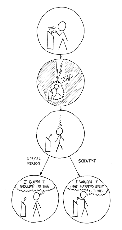
And now, the video... this one is their tamest one, and it's a pretty entertaining "dance" music video (almost kid friendly even, you'll have to be the judge). Funny as heck, imo :). As a warning, if you go and look at their other videos, you may not want to do it at work (some are very NSFW!). From Russia with wtf.

pheloniusfriar: (Default)
I am trying to calculate moon phases. I have given up. All of the software I have found is either crappy at calculating it (very loose approximations) or is encumbered with some form of licensing that I am not particularly interested in accepting. Almost all the good software points straight back at the book "Astronomical Algorithms" by Jean Meeus. Ultimately I will probably go that route and write my own software based on it (and release it with a proper open source license), but I've given up and am just going to type in a couple of years of data from tables (which says Permission is granted to reproduce this data when accompanied by a link to this page and the credit line: "Moon Phases Table courtesy of Fred Espenak, www.Astropixels.com"). Here is the page:

Six Millennium Catalog of Phases of the Moon: Moon Phases from -1999 to +4000 (2000 BCE to 4000 CE) by Fred Espenak

And yes, it says the tables were done with calculations based on the algorithms in "Astronomical Algorithms".

So great, I short circuit the process and have moon phases given to me. Each quarter phase (new, first quarter, full, last quarter) has a date and a UCT time (Universal Coordinated Time, aka GMT aka Z). The moon will be exactly that phase at exactly that time. However, to figure out when it's that phase where I am (or you are), I need to know what time zone I'm (you're) in.

I am in hell.

There is apparently no international standard for time zones. Wtf? The closest thing is the tzdb package that was a community project and is now maintained by the ... wait for it ... International Assigned Numbers Authority (IANA) which is responsible for Internet domain name roots (e.g. .com and .org), IP addresses, and protocol number assignments.

https://www.iana.org/time-zones

So, because the actual date of the phase of the moon could be one day on either side of the moon phase given in UCT (depending on whether you are east or west of the prime meridian), I now need to know timezone and offset and daylight savings time and, and, and... to figure out what day the moon phase will be at any given place. The problem is that there is no clear method of implementing this. All of the code support is around giving your operating system a time zone and having it convert the system time from local time to UCT or visa versa. There doesn't seem to be any clear mechanism to say, "hey, here's a time UCT and a timezone string, tell me what the time is there". There might be, but it is not apparent and there's an entire technical sub-language built around the subject that is opaque at first blush to thwart any chance of this being straightforward.

I do know that one of the first things I need to do is import the tzdb into MariaDB. Apparently when the database system is initialized, it creates all the tables necessary for the timezone information database, but it does not populate it, so I need to do something like (after installing the latest version of tzdb on my system, it updates when some politician decides to change a timezone or daylight savings thing):
mysql_tzinfo_to_sql /usr/share/zoneinfo | mysql -u root mysql -p
and then figure out what the heck to do with it. Ugh. This could be a full time job for months if I wanted to do it right, but I thought this was going to be one small detail near the end and that it wouldn't be a big deal. Hahahaha, fml.

Edit: I was reading documentation on how to update time zone information in MariaDB and it mentioned a function called CONVERT_TZ(). It takes a date and time, a from time zone, and a to time zone, and tells you the date and time in the to time zone. That is exactly what I needed to do (take the UCT date and time of a moon phase and convert it into the date and time in the target time zone). Sweet, and weeks of work short-circuited! There was a new moon at 03:47 UCT (24-hour time or bust) on October 9. Since I'm in the Canada/Eastern time zone (which is -4 or -5 hours depending on whether daylight savings time is in force or not), the new moon in my time zone is actually on October 8!
SELECT CONVERT_TZ('2018-10-09 03:47:00', 'UCT', 'Canada/Eastern');
+------------------------------------------------------------+
| CONVERT_TZ('2018-10-09 03:47:00', 'UCT', 'Canada/Eastern') |
+------------------------------------------------------------+
| 2018-10-08 23:47:00                                        |
+------------------------------------------------------------+
1 row in set (0.00 sec)
Great! The thing is that it was there the whole time, but this capability wasn't mentioned anywhere until I ran across an obscure corner of the documentation that talked about how to update the internal time zone information (Staying Current with Time Zone Changes) that mentioned the CONVERT_TZ() function. It also provided an example that seemed to do exactly what I wanted. No Google or DuckDuckGo search turned up anything about it. There was no way for me to know what question to ask even. This is a problem with modern complex software systems: even when there is good documentation, unless you read it cover to cover (a challenging proposition given that it's all only online these days)... and manage to remember it all for when you need to ask a question... much wasted work is engaged in as we each try to re-invent an already perfectly functional wheel.

P.S. I'm doing some cool stuff around equity, diversity, and inclusion in STEM fields and will write about it soon I hope.

Today's video is... odd... kind of adorable... and Brazilian.

Old dogs...

Sep. 8th, 2018 01:23 pm
pheloniusfriar: (Default)
I have been using the C programming language for startlingly close to 40 years, but I had occasion today to use three macro definition features of the C pre-processor that I have never (to my memory anyway) used before.

I wanted to automate the declaration of groups of variables I use over and over again. The variables all have different data types, a common prefix, and different suffixes, so things like "char *BOB_name;", "int BOB_count;", etc.. The problem is that if I define a substitution macro with arguments, it requires that the tag have whitespace around it, so something like "#define argh(TAG) char *TAG_name; int TAG_count" doesn't do any substitution. However, there is a feature that tells the pre-processor to concatenate the tag and whatever comes after it, and that is the "##" token:
#define argh(TAG) char *TAG ## _name; int TAG ## _count
(having the "*" right before the tag doesn't seem to be a problem). So specifying:
argh(BOB);
gives:
char *BOB_name; int BOB_count;
which is what I wanted.

The second thing combined two features: variable argument lists and wrapping a tag in double-quotes (which make it a string). The first is because I want to use the macro to invoke an actual variable-argument function, and the second is because the pre-processor won't do substitutions inside a string, so the "#" token before a tag in the substitution text tells it to add double quotes around the tag and put it there. The double quotes thing works well because if you specify "foo" "bar" in C, the compiler concatenates the two strings together to make "foobar", so you can make one of initial strings the tag and a properly formatted string will be produced. For the variable arguments, this has been supported since C99, but there is a subtlety that is needed to handle the case for when there are 0 arguments specified. Unfortunately, this wasn't in any specification until C++2a and gcc 8 (I'm using gcc 4.8 still). If supported, all together, this looks like:
#define spooge(TAG, search, ...) TAG ## _data = \
  find(connection, flag, TAG ## _fields, #TAG, search, __VA_OPT__(,) __VA_ARGS__)
(where the backslash indicates that the macro is continued on the next line). If I then write the following:
spooge(BOB, "where location = '%s'", location);
it expands as:
BOB_data = find(connection, flag, BOB_fields, "BOB", "where location = '%s', location);
Because of the "__VA_OPT__(,)" token, it will only put a comma in the expansion if there are arguments specified. So specifying:
spooge(BOB, "where location = 'cat tree'");
will expand as:
BOB_data = find(connection, flag, BOB_fields, "BOB", "where location = 'cat tree'");
(note the lack of comma after the "search" tag substitution). Also note that the last bit of these macros is specified without a semicolon. This is so that when the macro is invoked like any other C statement with a semicolon at the end, the substitution happens and then there's that semicolon at the end already (if you put a semicolon at the end of the macro, there would be two after the substitution, ";;", but it would be fine as the second would just be ignored, but... there's an elegance about doing it this way).

Unfortunately (I never come here with nice, happy programming stories), since the version of the compiler I have doesn't support the "__VA_OPT__(,)" feature, it just means that I have to specify at least one argument for it to work. Luckily, I have lots of parameters, so I just need to stop one argument early so I always have the "search" string as at least one variable argument:
#define spooge(TAG, ...) TAG ## _data = \
  find(connection, flag, TAG ## _fields, #TAG, __VA_ARGS__)
So when I invoke:
spooge(BOB, "where location = '%s'", location);
it expands as:
BOB_data = find(connection, flag, BOB_fields, "BOB", "where location = '%s', location);
where the "where..." string is just another variable argument, but one that is guaranteed to be there! Also:
spooge(BOB, "where location = 'cat tree'");
will expand as:
BOB_data = find(connection, flag, BOB_fields, "BOB", "where location = 'cat tree'");
again, because the "where..." string is a variable argument parameter now. It is not as elegant from a macro definition standpoint, but it accomplishes the same thing for me so I'm happy (or as happy as I can be stuck in front of my monitor on a lovely day in Ottawa... maybe I'll take a stroll later today...).

The next main thing I need to do is decide on a documentation tool for the code. I used ROBOdoc extensively about a decade ago (and still like it), but it appears to have fallen out of favour and isn't being actively developed anymore. For some reason, I really don't like Doxygen... I'm not sure why. The two contenders that I'm looking most closely at are Sphinx (which is written in Python and seems to be a popular choice these days), and the "literate programming" paradigm implemented with CWEB (Donald Knuth and Silvio Levy's game-changing system from the 1980s where you write a "web" that can either be tangled to generate C code or weaved to generate documentation for processing by the TeX document formatting language). The latter is the more powerful paradigm as it is document's one's thinking as the program is written rather than just pretty-printing the comments from the code.

And for today's music video (hopefully giving some value-add to your reading page rather than endless technobabble notes to myself as I work). I love the synth-dancy creatures:

pheloniusfriar: (Default)
Just a quick rant: UTF-8 is a character encoding that is used for almost all web sites and much electronic information these days. It has become ubiquitous. I am using MariaDB (which was a fork from MySQL after Oracle acquired it and fucked it up), and there is a character encoding that they call "utf8" that they inherited from MySQL. Unlike ASCII, which was ubiquitous before UTF-8 became dominant in about 2009. The main difference is that UTF-8 encodes for Unicode characters (which can represent just about every character and variant currently and historically in use globally) and can be 1 to 4 bytes long whereas ASCII is 7-bits and fits in 1 byte (with one bit left over, which gave rise to a plethora of other character encodings that used that upper bit to denote "extended characters", which is another reason why UTF-8 became so popular once it was introduced: one character encoding could be used for all characters). I use UTF-8 everywhere in the application I'm writing because it's the only sensible thing to do when multiple languages need to be supported.

I had a problem yesterday that I was storing strings in the database as UTF-8, and explicitly stated in the schema that the strings were "utf8", but I was getting gibberish in my query results (using the C API) any time the string contained a UTF-8 encoded character. Doing a bit of searching, I found that I needed to use the function call 'mysql_set_character_set(db_con, "utf8")' to tell the API to return the results in UTF-8 format (I have no idea what it was doing before). Problem solved. However, today I was looking to see if GNU m4 supported UTF-8 character encoding (it doesn't fyi, but there are workarounds, sigh), when I ran across references to MySQL and "utf8mb4" and mumblings about problems with "utf8". Upon further reading... holy fuck, what is the matter with people??? I implemented support in my application for UTF-8 from the start and it took nearly no effort, but the chuckleheads working on MySQL decided that they would only support a subset of UTF-8 and called it "utf8". They apparently quietly introduced a new character encoding called "utf8mb4" (again, searching for UTF-8 and m4 brought up this information randomly, which was lurking as a bomb for me to step on some time in the future thinking I was moving in safe territory). Apparently, this encoding properly supports the full UTF-8 character encoding set.

This article gives an excellent overview of the issue: In MySQL, never use “utf8”. Use “utf8mb4”. Fuuuuuu.

As the saying goes, "if builders built buildings the way programmers wrote programs, then one woodpecker could destroy the entirety of civilisation".

Ugh.

Here's a guide on how to convert from "utf8" to "utf8mb4" if you, like me, have found yourself bitten by this lossage: How to support full Unicode in MySQL databases. The connection and client information should probably also be updated: "SHOW VARIABLES WHERE Variable_name LIKE 'character\_set\_%' OR Variable_name LIKE 'collation%';".

I also don't have a lot of polite things to say about a program like m4 not natively supporting UTF-8 in 2018. I tried to volunteer to write the necessary changes (and may still do it as part of wanting to contribute back to open source projects I use), but the web site I found was apparently abandoned and the email address they had against the "hey, we need to implement UTF-8 would you like to volunteer?" entry bounced. There is a more modern site, but they don't really list UTF-8 as a task available for doing. Their statement on multi-byte characters is: GNU m4 does not yet understand multibyte locales; all operations are byte-oriented rather than character-oriented (although if your locale uses a single byte encoding, such as ISO-8859-1, you will not notice a difference). However, m4 is eight-bit clean, so you can use non-ASCII characters in quoted strings (see Changequote), comments (see Changecom), and macro names (see Indir), with the exception of the NUL character (the zero byte ‘'\0'’). m4 is niche, but this makes it even more niche, and I may just write my own text UTF-8 aware text substitution program to do the work I need and just ditch m4.

For those that have the sense to skip my technobabble, here's an absolutely delightful music video with some tremendous visuals and fun music and people (and a cat in a diving suit?).

Yeep!

Aug. 29th, 2018 09:54 pm
pheloniusfriar: (Default)
I tried to connect to my server from work earlier today and it did not respond. We had some serious storms go through the area today so I figured here was a power outage that lasted longer than the short time I have in my little UPS (there were reports of possible tornadoes just to the east of the city, still waiting to hear news of whether there was or not... although a hundred thousand people were without power in the Montreal area earlier, many are still waiting for power to be restored). I asked Beep to turn on the server when they got home and said they did... except, it was my flight simulator that they turned on, heh. Not a big deal, but I went down to turn it on myself when I got home.

Nothing.

No fan. No lights. No nothing.

Unplugged from UPS and plugged directly into the wall.

Not a whisper or stir of life. <gulp> <sweatles>

Had to run out and do some errands, but when I came home, I hauled the server upstairs to work on it, cracked a bottle of 2010 Monasterio de las Viñas Grand Reserva, and started to work. Pulled out the power supply and opened it up. Checked the internal fuse: it was fine. Got a jumper wire and shorted the PS_ON signal (green wire) to the ground beside it (black wire), plugged in the supply and ... nothing at all. Turned it off and there was a weird hissing noise for a few seconds and then silence. Being a scientist, I did it again with identical results.


'nuf said ;).

This was potentially good news because I was then sure the power supply was fried, and that might be the only problem, but I didn't know yet whether the motherboard or any other parts got cooked at the same time.

I had a spare power supply from a previous system I had built, but had to remove to upgrade to a newer power supply when I got a fancy graphics card for it that needed additional power, so I went down to the basement to get that. I tried the PS_ON trick and the fan started to turn, so that was a good sign. I installed it in the system (it was better suited for the server than the one I had in there it turns out), connected everything up, plugged it in, turned on the system, and ... power lights. I turned it off right away before it could boot (it runs Linux), and brought it down, hooked it up, and boop, beep, blorp it came up perfectly the first time!

<phew!>

I do regular backups, but I just did some intense coding the past couple of days and had not done one in the interim, so that would have been a serious pisser if I'd lost the hard drives, for instance (I find it really hard to rewrite code after it has been lost, I don't know why it gives me extra grief beyond the basic annoyance of having to do it).

So crisis averted, and the wine turned out to be very, very nice.

I leave you with this absolutely delightful music video... the animation is wondrous!

Profile

pheloniusfriar: (Default)
pheloniusfriar

May 2025

S M T W T F S
    123
45678 910
11121314151617
1819202122 2324
25262728293031

Syndicate

RSS Atom

Most Popular Tags

Style Credit

Expand Cut Tags

No cut tags
Page generated Jan. 5th, 2026 08:12 pm
Powered by Dreamwidth Studios