
Entry tags:
PWM Audio from Flash with PSoC 4
Copying another post I made on the Cypress/Infineon user forum here so I have it myself.
I have written an article on my blog on the process I followed to get an audio clip into a PSoC 4200 MCU (I used the CY8CKIT-049-42xx PSoC 4 Prototyping Kit), and play it back using a TCPWM component. I start with a 44.1kHz 16-bit PCM stereo audio recording (CD quality), and go step-by-step on how to process the audio, reduce the dynamic range (bits per sample) and the sampling rate to reduce the number of bits needed for the clip, how to program the samples into flash so they're accessible to an interrupt handler, and how to use a PWM technique to generate the analog output of the audio. I provide instructions on what is needed with respect to filtering and amplification, but don't go into detail (that's for another post another time probably). I did use the two on-chip op-amps with a few resistors and capacitors to implement a 4th order Chebychev filter and then used an off-the-shelf audio amplifier to drive a speaker. Other than PSoC Creator, all of the software I used is open source or are simple little C programs I wrote myself (and provide instructions on how to duplicate). Spoiler alert: I got about 1.4 seconds of 11-bit 11.025kHz linear PCM audio into the chip (which takes about two thirds of the flash memory). If that's not enough, there are some serial (SPI) flash memories that can hold about 9 minutes at that rate/sample depth (<$4 in qty. 1). I implemented this on a PSoC 4200, but the technique is quite general (and can be used with MCUs that have proper DACs as well).
Here's the link: Stuffing an audio file into a tiny processor chip
In response, someone [odissey1] asked me if I could post the project code, so...
Project file or it never happened, eh? Fair enough. Please find attached.
1kHz_PWM_Audio_Demo_v1.0 project file is here!
The archive contains a project targeted at the CY8CKIT-049-42xx PSoC 4200 prototyping kit (including it's use of the bootloader component); but the schematic, TCPWM configuration, and source code should be easily adaptable to any PSoC target with a TCPWM component (the C code is mostly generic with a few PSoC specific commands to set things up). The CY8CKIT-049-42xx bootloader files are there too so it should compile right out of the .zip file without reconfiguration if you have one lying around. I have also included a simple audio data file ("sine_1kHz.dat") that has a 1kHz sine wave sampled in it that the code just repeats over and over again (and outputs on P3.0 for this project).
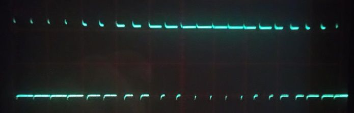
Here's a bad photo taken with my terrible phone using a sad oscilloscope of the PWM data output on a pin (you can see the density of the PWM signal changing).
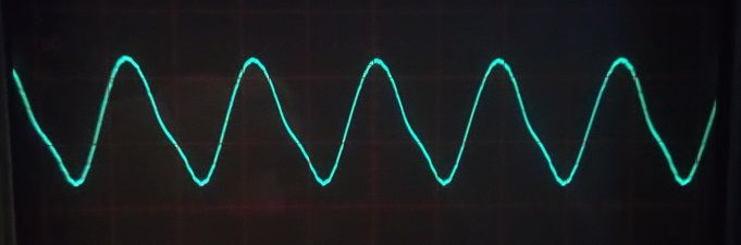
Here's another bad photo taken with my terrible phone using a sad oscilloscope of the output from the not so great filter circuit using the PSoC 4200's on-chip op-amps. Note that there is a fair amount of distortion in the sine wave... the filter really isn't that good, but it's still good enough for what I needed it for. Also note that the 'scope is set to 2V/div and 0.5ms/div, and that the ground potential is the graticule below the waveform, so you can see that the centre of the sine wave (the common mode voltage) is indeed at about 1/2 of the supply voltage of the PSoC 4200 (5V... powered off the USB interface of the CY8CKIT-049-42xx). The filter could be made much better if the digital PWM signal were run through a divider first and if I were a little more careful with the component selection (but the lack of a SPICE model for the on-chip op-amps makes doing a great job a little harder).
Hopefully this proves useful.
As an aside, this project file is intended for use with the PSoC_Creator Integrated Development Environment. As a write this, it is available for free download (it was always free) at: https://www.infineon.com/cms/en/design-support/tools/sdk/psoc-software/psoc-creator/
They then asked (reasonably enough), "Do you have any idea why the sine output looks asymmetric? Is this the effect of the Chebyshev filter or intended PCM signal?"
And my answer:
There are a bunch of reasons why the "sine" is not so sinusoidal, where to start? The filter components I used were built on a little breadboard PCB plugged onto connectors I put on the CY8CKIT-049-42xx and the circuit has no particularly effective ground, so there are all kinds of basic signal integrity problems. The sine wave only has 14 samples (that I kind of randomly chose... the samples are not symmetric and the knee might simply be from looping), so it's going to be pretty choppy no matter what (it would be that way even with a proper DAC), but the problem is compounded by using a PWM and asking a sub-optimal filter circuit to do a lot of heavy lifting in filtering out that digital signal. The filter circuit itself doesn't have the exact component values I wanted because I didn't have those values on hand, so it's approximate in its performance that way too. If I wasn't swinging nearly 5V peak-to-peak I think that would help a lot as well. The op-amps on the PSoC 4200 kind of suck in terms of their performance, and using a filter built with good quality external components would give a much better result (my early attempts were nightmarish, so the distortion here is actually a huge step forward from where I started). Lastly, the lack of a SPICE model for the on-chip op-amps meant that I couldn't really tune the filter circuit nicely to the op-amp performance and just kind of did things empiirically. I know I could do better even using the on-chip op-amps, but that's a project for another day. Ultimately, I was completely successful in what I was trying to do, which was to only use a CY8CKIT-049-42xx that I had (with a few external passive components) to drive an amplifier and little speaker with a short audio clip. In the context that I was using it, and with the audio clip I had, the sound coming out was entirely acceptable (even with whatever distortion it would have).
After looking at the code for the project I provided they said, "The code is certainly not trivial. My guess that most of the complexity comes from extracting the 11-bit audio from the 8-bit storage array. Is there any audio software capable of such packing or you had to post-process PCM data?"
So...
I just used open source software to get the data into a format where I could pack the 11-bit samples with my own code (into 8-bit bytes). As I wrote in my "article", I did it in two stages: the first little program took it from 16-bit signed PCM (in a RAW file format, that had already had its dynamic range squashed to 11-bits) and wrote it out to disk as a 11-bit samples packed together as a data stream (written out 8-bits at a time to disk), then another little program to convert the byte-stream into comma-separated ASCII for loading into the C compiler uint8_t array when it compiled.
I didn't post the code for the audio conversion at the time, but here it is in all its (lack of) glory for posterity. Very simple code, but tricky to get right.
First, compile "encode_raw.c" and "enc2dat.c" (filenames are links to C code files).
Follow the instructions in the article I wrote to get a RAW audio file (the instructions are relatively clear in my opinion). Then run the encode_raw program:
This will generate a binary file filename.enc that contains the packed 11-bit PCM audio data. The run the enc2dat program:
This will generate a text file filename.dat that contains the data for including in the final project code like so:
This initializes the uint8_t array with the audio data that the program's code will need to pull out as an 11-bit PCM stream (from the array of 8-bit values). I thought this was a fairly clever way of doing it as it allowed this arbitrary audio data to be programmed into Flash along with the program code. If more data space was needed (the chip I was using only had 32K of Flash for programs and data), then an externally connected Flash chip could be used.
And for anyone who scrolled by, here's a non-technobabble gift. Show 25 from Season 1... Note: this episode is Not Safe For Work (NSFW) and full of various naughty bits (every 25th show will be a collection of the naughtier songs and videos I have run across so they're all in one place and are easier to avoid and/or focus on).
I have written an article on my blog on the process I followed to get an audio clip into a PSoC 4200 MCU (I used the CY8CKIT-049-42xx PSoC 4 Prototyping Kit), and play it back using a TCPWM component. I start with a 44.1kHz 16-bit PCM stereo audio recording (CD quality), and go step-by-step on how to process the audio, reduce the dynamic range (bits per sample) and the sampling rate to reduce the number of bits needed for the clip, how to program the samples into flash so they're accessible to an interrupt handler, and how to use a PWM technique to generate the analog output of the audio. I provide instructions on what is needed with respect to filtering and amplification, but don't go into detail (that's for another post another time probably). I did use the two on-chip op-amps with a few resistors and capacitors to implement a 4th order Chebychev filter and then used an off-the-shelf audio amplifier to drive a speaker. Other than PSoC Creator, all of the software I used is open source or are simple little C programs I wrote myself (and provide instructions on how to duplicate). Spoiler alert: I got about 1.4 seconds of 11-bit 11.025kHz linear PCM audio into the chip (which takes about two thirds of the flash memory). If that's not enough, there are some serial (SPI) flash memories that can hold about 9 minutes at that rate/sample depth (<$4 in qty. 1). I implemented this on a PSoC 4200, but the technique is quite general (and can be used with MCUs that have proper DACs as well).
Here's the link: Stuffing an audio file into a tiny processor chip
In response, someone [odissey1] asked me if I could post the project code, so...
Project file or it never happened, eh? Fair enough. Please find attached.
1kHz_PWM_Audio_Demo_v1.0 project file is here!
The archive contains a project targeted at the CY8CKIT-049-42xx PSoC 4200 prototyping kit (including it's use of the bootloader component); but the schematic, TCPWM configuration, and source code should be easily adaptable to any PSoC target with a TCPWM component (the C code is mostly generic with a few PSoC specific commands to set things up). The CY8CKIT-049-42xx bootloader files are there too so it should compile right out of the .zip file without reconfiguration if you have one lying around. I have also included a simple audio data file ("sine_1kHz.dat") that has a 1kHz sine wave sampled in it that the code just repeats over and over again (and outputs on P3.0 for this project).
Here's a bad photo taken with my terrible phone using a sad oscilloscope of the PWM data output on a pin (you can see the density of the PWM signal changing).
Here's another bad photo taken with my terrible phone using a sad oscilloscope of the output from the not so great filter circuit using the PSoC 4200's on-chip op-amps. Note that there is a fair amount of distortion in the sine wave... the filter really isn't that good, but it's still good enough for what I needed it for. Also note that the 'scope is set to 2V/div and 0.5ms/div, and that the ground potential is the graticule below the waveform, so you can see that the centre of the sine wave (the common mode voltage) is indeed at about 1/2 of the supply voltage of the PSoC 4200 (5V... powered off the USB interface of the CY8CKIT-049-42xx). The filter could be made much better if the digital PWM signal were run through a divider first and if I were a little more careful with the component selection (but the lack of a SPICE model for the on-chip op-amps makes doing a great job a little harder).
Hopefully this proves useful.
As an aside, this project file is intended for use with the PSoC_Creator Integrated Development Environment. As a write this, it is available for free download (it was always free) at: https://www.infineon.com/cms/en/design-support/tools/sdk/psoc-software/psoc-creator/
They then asked (reasonably enough), "Do you have any idea why the sine output looks asymmetric? Is this the effect of the Chebyshev filter or intended PCM signal?"
And my answer:
There are a bunch of reasons why the "sine" is not so sinusoidal, where to start? The filter components I used were built on a little breadboard PCB plugged onto connectors I put on the CY8CKIT-049-42xx and the circuit has no particularly effective ground, so there are all kinds of basic signal integrity problems. The sine wave only has 14 samples (that I kind of randomly chose... the samples are not symmetric and the knee might simply be from looping), so it's going to be pretty choppy no matter what (it would be that way even with a proper DAC), but the problem is compounded by using a PWM and asking a sub-optimal filter circuit to do a lot of heavy lifting in filtering out that digital signal. The filter circuit itself doesn't have the exact component values I wanted because I didn't have those values on hand, so it's approximate in its performance that way too. If I wasn't swinging nearly 5V peak-to-peak I think that would help a lot as well. The op-amps on the PSoC 4200 kind of suck in terms of their performance, and using a filter built with good quality external components would give a much better result (my early attempts were nightmarish, so the distortion here is actually a huge step forward from where I started). Lastly, the lack of a SPICE model for the on-chip op-amps meant that I couldn't really tune the filter circuit nicely to the op-amp performance and just kind of did things empiirically. I know I could do better even using the on-chip op-amps, but that's a project for another day. Ultimately, I was completely successful in what I was trying to do, which was to only use a CY8CKIT-049-42xx that I had (with a few external passive components) to drive an amplifier and little speaker with a short audio clip. In the context that I was using it, and with the audio clip I had, the sound coming out was entirely acceptable (even with whatever distortion it would have).
After looking at the code for the project I provided they said, "The code is certainly not trivial. My guess that most of the complexity comes from extracting the 11-bit audio from the 8-bit storage array. Is there any audio software capable of such packing or you had to post-process PCM data?"
So...
I just used open source software to get the data into a format where I could pack the 11-bit samples with my own code (into 8-bit bytes). As I wrote in my "article", I did it in two stages: the first little program took it from 16-bit signed PCM (in a RAW file format, that had already had its dynamic range squashed to 11-bits) and wrote it out to disk as a 11-bit samples packed together as a data stream (written out 8-bits at a time to disk), then another little program to convert the byte-stream into comma-separated ASCII for loading into the C compiler uint8_t array when it compiled.
I didn't post the code for the audio conversion at the time, but here it is in all its (lack of) glory for posterity. Very simple code, but tricky to get right.
First, compile "encode_raw.c" and "enc2dat.c" (filenames are links to C code files).
Follow the instructions in the article I wrote to get a RAW audio file (the instructions are relatively clear in my opinion). Then run the encode_raw program:
encode_raw filename.rawThis will generate a binary file filename.enc that contains the packed 11-bit PCM audio data. The run the enc2dat program:
enc2dat filename.encThis will generate a text file filename.dat that contains the data for including in the final project code like so:
const uint8_t audio_data [] = {
#include filename.dat"  // Put comma separated values audio samples file here
};
This initializes the uint8_t array with the audio data that the program's code will need to pull out as an 11-bit PCM stream (from the array of 8-bit values). I thought this was a fairly clever way of doing it as it allowed this arbitrary audio data to be programmed into Flash along with the program code. If more data space was needed (the chip I was using only had 32K of Flash for programs and data), then an externally connected Flash chip could be used.
And for anyone who scrolled by, here's a non-technobabble gift. Show 25 from Season 1... Note: this episode is Not Safe For Work (NSFW) and full of various naughty bits (every 25th show will be a collection of the naughtier songs and videos I have run across so they're all in one place and are easier to avoid and/or focus on).


